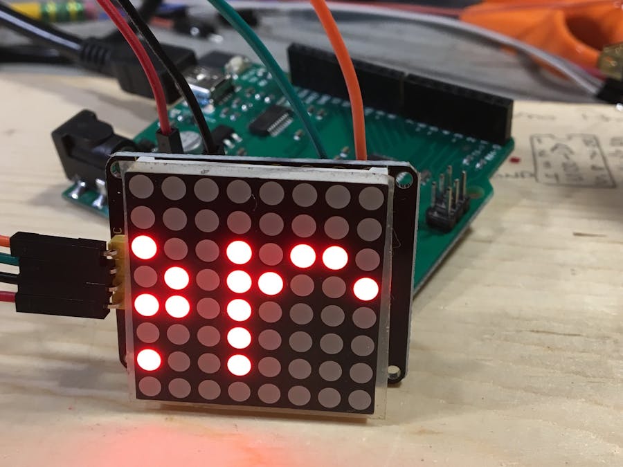
This is an older project I had sitting in my draft bin here at huckster.io. Since I just finished up a clock project with this same display, I dusted it off and finished it quick to publish.
Let's take a closer look.In one of my recent orders I tossed in a couple different displays. We live in a visual world lets add some beauty to it. One of the first displays I pulled out was the 8x8 LED matrix with the HT16K33 backpack. I have seen them before and to be honest I got it because it looked fun.
I can see it being used in a Christmas ornament, geeky little scrolling text gift, maybe a new way to display digits with my shakey dice project. Stick a few of them together and make a clock?
Before I get a head of myself, lets get this up and working first.
I took a look at the data sheet to see what I was getting into. You can find a copy of it linked here. The HT16K33 is a memory mapping LED controller meaning that display points are setup/mapped out in RAM before writing them out to the LEDs. From the data sheet "The display RAM is a static 16×8-bit RAM which stores the LED data. Logic “1” in the RAM bit-map indicates the “on” state of the corresponding LED Row; similarly, a logic 0 indicates the “off” state. There is a one-to-one correspondence between the RAM addresses and the Row outputs". The data sheet is actually a pretty interesting.
Wiring it up is straight forward as it uses I2C for communication. And yes, which means there can be more then one wired up and used at the same time. I have 2 of them, so once I get comfortable with one, there will be another write up for using multiples. It requires 4.5-5.5v for operation. The 5v from my board has been running it fine.
Wire it Up
Module Arduino
SCL ----- A5
SDA ----- A4
Gnd ----- Ground
Vcc ----- 5v
Once I have it wired up I like to run an I2C Scanner to make sure the device is up and running and also to confirm what address it will be using. After running it on this display I found it to have the address of 0x70. The address is usually changed via hardware. It is possible to override it in a sketch. In one instance, I had to change the address in the library before the device would work.
Libraries
Before we can start to work on our sketches it is time to get some libraries. I am using the Adafruit libraries. I have been very impressed with the work they have put into the libraries they create. Help support them when you can. Download and install
The Adafruit_LED_Backpack library and Adafruit-GFX-Library found out on Github are used for this write-up. They need to be installed into your ArduionSketchFolder/libraries (e.g. /Users/user/Documents/Arduino/libraries. If there isn't a folder, it may be the first library being installed. In that case, create a folder named libraries.
I find an easier way is to use the Arduino IDE Library manger. You can install them from within the IDE and it will keep an eye out if there are any updates. You can find it in the IDE Sketch -> Include Library -> Manage Library. From there you can search for a library. You won't find all libraries here, but a good many of them.
Make it do something already!
Here we go. The first sketch is little more than turn on LEDs to light up a T. I do this to make sure I know where 0, 0 is for sure also.
// For I2C
#include <Wire.h>
// Libraries for Matrix
#include "Adafruit_LEDBackpack.h"
#include "Adafruit_GFX.h"
Adafruit_8x8matrix matrix = Adafruit_8x8matrix();
void setup() {
 Serial.begin(9600);
 // Good idea to send data to both
 // device and serial as it helps with
 // troubleshooting.
 Serial.println("8x8 LED Matrix Test");
 // set the address
 matrix.begin(0x70);
}

void loop() {
 // Make sure where led 0x0 is:
 // And it is working
 matrix.setTextSize(1);
 matrix.setTextColor(LED_ON);
   // clear the matrix
   matrix.clear();
   // position the cursor
   matrix.setCursor(0,0);
   // text to print
   matrix.print("T");
   // write the data out to the matrix
   matrix.writeDisplay();
 // how fast the characters are displayed
   delay(150);
 }
Do you see the T? Cool, onward.
Lets make it scroll.
One of the cool things (I think) about these displays are using them to scroll text. This simple sketch is going to scroll a word across the screen. You can download the code and check it out.
Oh, a sidenote. The way this display works is by setting up the screen (if you will) in buffer space and then writing it out. If you look in the loop you can see where is matrix is setup, once set the last thing it does it write the buffer out.
Geometery
Since the display is little more than a matrix of dots, it only makes sense we can make shapes, so lets see how we can do that next.
To turn on a dot
void loop() {
 // clear display
 matrix.clear();
 // set pixel x,y to ON
 matrix.drawPixel(0, 0, LED_ON);
 // write RAM to matrix
 matrix.writeDisplay();
 delay(500);
 }
Next lets draw a line
void loop() {
 // clear display
 matrix.clear();
 // set (start pixel x,y end pixel, ON)
 matrix.drawLine(0,0, 7,7, LED_ON);
 // write RAM to matrix
 matrix.writeDisplay();
 delay(500);
 }
Defined shapes
The Adafruit library has predefined shapes we can use such a rectangle and circle. Lets take a quick look at one.
void loop() {
 // clear display
 matrix.clear();
 // draw a retangle around the outer edge
 // of the display
 matrix.drawRect(0,0, 8,8, LED_ON);
 // uncomment below
 // will draw a rectangle arond the edge and
 // fill it in, ie. turn on all of the LEDs
 //matrix.fillRect(0,0, 8,8, LED_ON);
 // write the changes to the display
 matrix.writeDisplay();
 delay(500);
 }
The example above shows how to draw a square outlining the display. The commented section will fill in the whole display. Try making the fill x, y with something like 3, 3 5, 5 to get different fills to occur.
That is a quick look at this little display. I have just started working and playing with it. And will be posting any other fun information I can glean from others and my own playing around with it.
I am off to start working on a couple of gifts for people.
If you have used them, I would like to hear from you as to how and what you used yours for.


_ztBMuBhMHo.jpg?auto=compress%2Cformat&w=48&h=48&fit=fill&bg=ffffff)


Comments
Please log in or sign up to comment.