


Hardware components | ||||||
 |
| × | 1 | |||
| × | 1 | ||||
 |
| × | 1 | |||
 |
| × | 1 | |||
 |
| × | 1 | |||
The new boards are in hot off the press! I have dry fitted one of them and a quick continuity test. I am ready to solder it up tonight when I get home from work.
I already see one issue, and am working on a minor change to it.
Idea and planning:My daughter wanted some colored blinking lights for her new loft bed. They had to stay a solid color and blink. I headed down to the workshop to see what I could come up with.
I have used the ESP8266-FastLed-WebServer software before and it works quite well. 2 thumbs up to Jason for all of his hard work. So with the software taken care of all I had to do was to focus on the hardware. To be honest I like the hardware side of things a little better than the software.
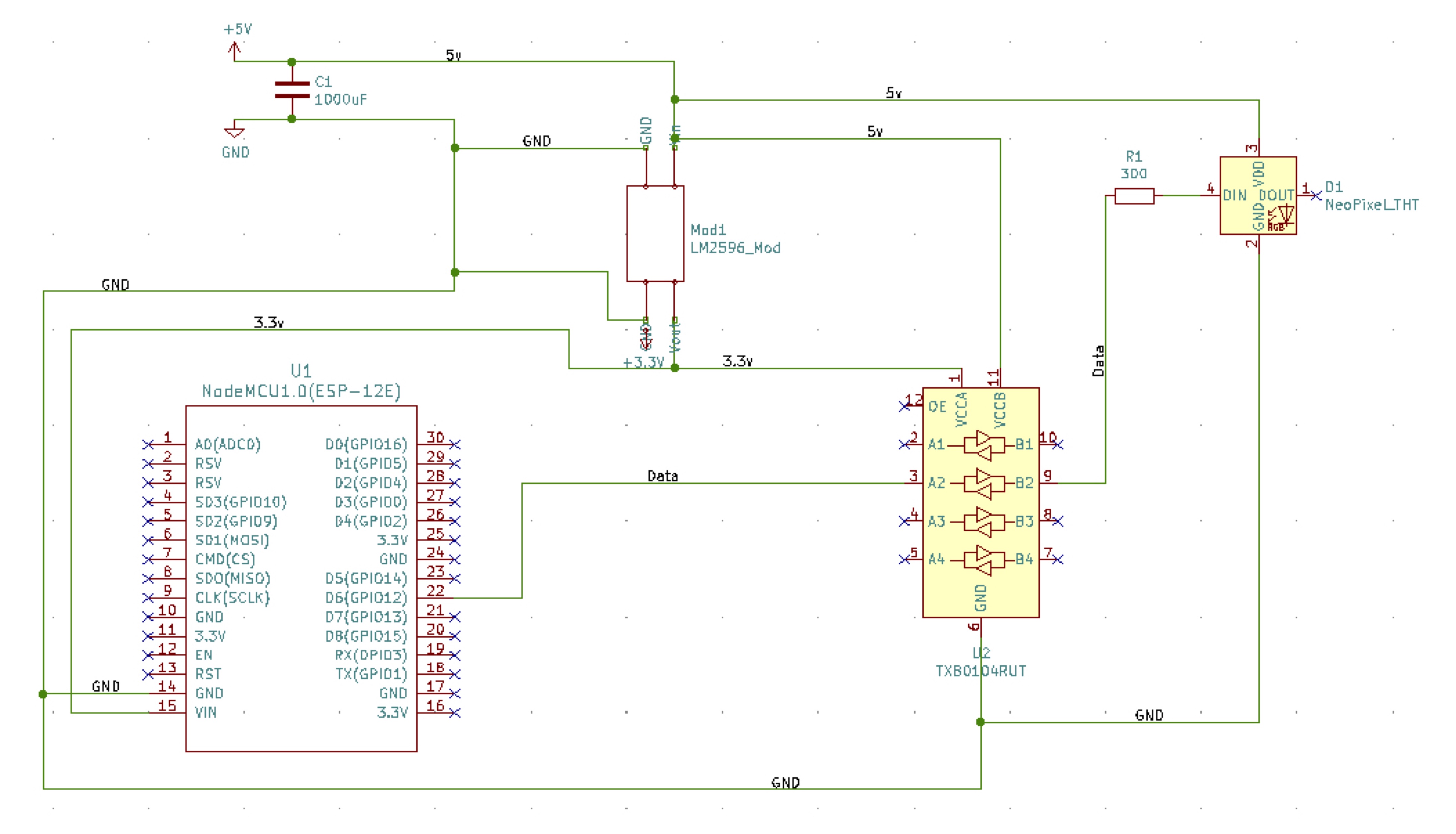
The hardware plan is pretty simple. The three main parts being the ESP8266 for processing and communications, DC-DC step down for the power, logic level shifter for the data signal line.
I rummaged around the workbench and came up with:
Amica NodeMCU v2
4-channel logic level shifter breakout board
LM2596 power module
1x 100uF a cap
1x 330 Ohm resistor
1x 2.1mm DC Barrel Jack
Length of WS2818 5v RGB LEDs. I used 1 meter.
Putting it all togetherI dialed in the power module down to 3.3v. It is variable which is very nice. I keep a couple of them around to provide a quick and stable 3.3v power to some of my projects.
I have a barrel jack providing 5v from a wall wart. It runs into the M2596 tha I have set down to 3.3v for the NodeMCU. It uses a variable resistor to control the voltage level. The adjustment on it is pretty fine and I haven't had any issue with it drifting once it is set. Note: I still need to run 5v to the LEDs and then also to the 4-channel Logic Level Shifter.
This is the only part that can get tricky. The LLS has two sides a low and high side indicated by the L and H. The low side will see connections to 3.3v, GND, and Pin 6 of the NodeMCU. The high side will see 5v, GND, and data out to the LEDs. A resistor is place inline to the data line into the LEDs. This is done per best practices to protect the data line.
I ran a pig tail of through a hole in the case. Then the three wires are connected inside. It is a quick connector that came with the lights. I just added the pins to the ends for quick and easy connections here. The Red goes to 5v, the White goes to GND, and the Green is the data line.
The NodeMCU sees a 3.3v wire for power, Ground, and a connection to Pin 6 from the LLS to control the LEDs.
Alright, things seem to work on the bench just fine, now it is time to wire it up while in the case to make sure everything works before I button it up.
The case was a fun part. I wandered through my bin of boxes and things that look like enclosures and stumbled upon this one I had used a couple of years back.
I had some lights outside and needed and case to weather the elements and Black and Decker battery pack (emptied) worked out quite well, so decided to give it a second life.
As I worked on this project I kept on getting ideas for a quick PCB to make this easier and look a little neater. I designed a PCB in KiCAD and simplified things a bit by using a 74HC125 for the LLS and a LM1117 3.3 for the power step down.
The board is being made by PCBway.com. I have not used them before and tried them on a whim really. My fingers are crossed.
You can keep up with the progress of this project over at my website https://www.wrightmac.net.
Version 2 will remove the NodeMCU and use an ESP8266 module.


_3u05Tpwasz.png?auto=compress%2Cformat&w=40&h=40&fit=fillmax&bg=fff&dpr=2)
Comments
Please log in or sign up to comment.