


Table lamps come in all shapes sizes and styles to suit a variety of purposes.
So in deciding to make one a conscious effort was made to explore a different style whilst adjustability was still a requirement.
The head of the lamp would be in the form of an adjustable flower with a glow disc and adjustable shield.
Taking inspiration from the human body and more specifically the hip joint for the main articulating element.
This would take the form of a monostatic object in this case a sphere were one hemishpere is weighted.
At first glance this gives uncontrolled positioning with the light at the end of a long arm light that defeats the desired adjustability however, if we mount the ball in a raised hollow cylinder (akin to a truncated socket); coupled with a surface that is not too smooth. The ball can be repositioned and retain its position.
Therefore major manipulation can be carried out by repositioning the ball with smaller adjustments made at the head.
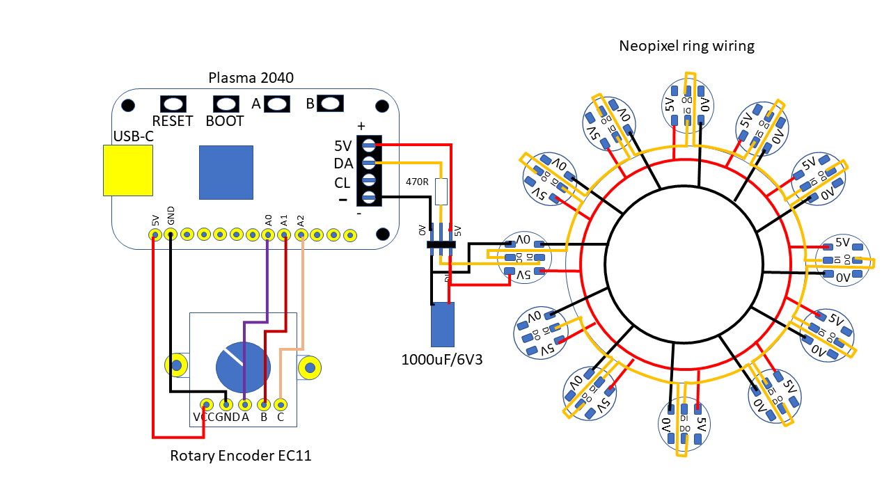
Whilst the weighted ball counterbalances the head containing the light source it also contains the control element in the form of a Plasma 2040.
DesignAll the 3D printed parts were designed in BlocksCAD
These consist of the following elements.
1: Rear petals.
2: Front petals with integral shield and control knob.
3: Middle petals with LED's and head adjuster. (2 x parts)
4: Support Grid
5: Hollow ball. (2 x hemispheres)
6: Base.
7: Stalk support (3 x parts)
AssemblyFit the LED's
The 12 Neopixels fit into the circular depressions in the middle petals and are wired in a ring power configuration and serially data linked using the grooves to form and retain the wires.
Three flexible multistrand wires ~80mm in length are now required to connect the supply and the Din line.
Connect a wire to the first designated LED in the chain at Din, connect one to a point on the 0V ring and another wire on the 5V ring.
Solder or crimp a 3 pin connector on the end on these wires, ensure the correct types are fitted to match with corresponding connectors on both the flower and the long wires.
Stalk
The stalk is made up of a hollow stainless steel tube 34cm (L) x 6mm dia.
Fit 2 x M3 x 10mm hollow standoffs in each end.
Make a mark on the tube 10mm above the top of the tube support and at this point drill a 3mm hole and deburr the edges with a round needle file.
Twist the 3 lengths of multistrand wire together and thread down through the hole in the standoff and out through the 3mm hole in the side.
Slide the heat shrink sleeving over both ends of the wire and slide into the standoff and at the other end slide into the 3mm hole which will protect the wire from chafing.
Strip the wires and fit a SIL connector to the bottom end, ensure the correct types are fitted to match with corresponding connectors on both the flower and the microcontroller.
Flower Head
The flower is constructed as a stack held together by a set of 12 screws which are all inserted from the front and through to the back. The shield also pivots on these screws to allow the light to be shielded to create a mood light.
Position the back petal element with the standoffs facing upward.
Align the middle petal element with the LED front facing upward and the outer holes aligned with the back petal element.
Place the glow disc over the middle petal and align the holes on the disc with the outer holes on the middle petal element.
The glow disc is made from an Acrylic disc (120 mm x 1 mm), with 12 x 2mm holes on a 45mm radius which align with the outer holes of the petal element containing the LED's.
Align the front petal element over the glow disc and align the slots with the hole.
Fit the 12 x M2 x 12mm self tapping screws through the slot and into the aligned holes and tighted until the screw head only lightly touches the front petal element. There should be some play between the front petal element and the screw head this will allow the front petal element to rotate freely from left to right, revealing or obscuring the LED's.
Fit the articulated joint to the stalk with a M4 x 10mm bolt.
Ensure the correct types are fitted to match with corresponding connectors on both the flower and the wire from the microcontroller. Join the connectors on the wire and the flower head.
Lower Hemisphere
The lower hemisphere with the centred stalk support is filled with cement.
The grid supports the microcontroller and the USB interface cable and is held in place with a M4 x 20mm bolt that also holds the stalk in place.
Insert the stalk into the support and connect the wire to the microcontroller.
Attach the microcontroller with 3 x M2 x 8mm screws positioned over to the right on the delta supports. This is to ensure the right angle USB plug does not catch on the upper hemisphere. Similarly with the LED strip terminals.
Fit two M3 X 5mm standoffs to the rotary encoder.
Upper Hemisphere
Lower the upper hemisphere down to allow the encoder spindle to fit through the centre hole and align the standoff with the two holes. Attach the encoder to the hemisphere with 2 x M3 x 6mm screws and fit the knob on the spindle.
Align the back of the hemisphere with the USB socket and fix in place with 2 x M3 X 6mm screws.
The sphere is held together with 12 x M2 x 6mm self tapping screws around the circumference.
Base
The bottom hemisphere sits in the base ring and allows you to position the ball in a number of different positions to direct the light as required.
The base itself should sit on a flat non slip surface to prevent movement as the ball is positioned.
The inner rim of the base as printed will likely be a little slippery to support the light at a very acute angle and subject to the surface finish of the filament used.
The join between the two hemispheres in conjunction with the base serves to prevent the angle of the lamp stalk exceeding 55 degrees.
Stick a ring of non slip matting or similar material on the inner support rim of the base.
Sit the base on a non siip mat, if the surface it will sit on is slippery.
Insert the USB lead into the socket at the back and insert into a compatible adapter.
Position the circular base in a suitable location and sit the ball on top.
There is no separate on/off switch everything is controlled by the encoder.
Main adjustment is accomplished by positioning the ball on the base, small adjustments are made by tilting the flower head.
The start up default is all LED's off.
Turn the button left or right to step through the colours, stop turning when the required colour is visible.
The LED's can also be turned off in this mode by rotation of the control.
Press the button to change to intensity mode.
(Default intensity mode is 100%)
Turn the button left or right to adjust the intensity, stop turning when the required intensity is achieved.
Press the button to return to colour setting mode.
The Intensity setting will be applied to all the colours in this mode unless it is subsequently changed.
The greatest time duration for this project is in the 3D printing taking ~36 hours.
In addition to this the curing time for the cement, which ideally should be left to cure in a warm room, subject to curing time and mineral crystallisation on the surface.
Further details can be found here:
Balanced Lighting : 16 Steps (with Pictures) - Instructables


Comments
Please log in or sign up to comment.