


Hardware components | ||||||
 |
| × | 1 | |||
 |
| × | 1 | |||
| × | 1 | ||||
| × | 1 | ||||
 |
| × | 1 | |||
 |
| × | 1 | |||
This project is a WordNum clock being a hybrid of a Wordclock and a digital clock using 100 addressible RGB LED's controlled by a Microbit with an RTC.
Displaying the time in 12 hour mode and updated each minute with the addition of text each 5 minutes.
The display and main supporting structure is 3D printed and this is mounted within a deep picture frame.
The project can be mounted with or without a frame supject to the frame size a retainer may be required.
An Acrylic retainer creates a border and support for the Character Board centring it in the frame.
The retainer was created for a frame that was purchased from a used goods store which fitted my decorative requirements for this project therefore subject to requirements the retainer may be sized or omitted as fits the users tastes.
A frame depth of 40mm with the circuit as mounted would keep the circuit from pressing against the wall.
If a frame with a depth of <40mm is used the difference in depth can be made up with a supporting box section made from wood or perspex and used to facilitate hanging.
For the frame used the Acrylic sheet is cut to the inner frame dimensions, the glass in the frame was used as a template.
Size: 206(L) x 206(W) x 40(H) mm (excluding framing).
Currrent: <=200mA at 5V
This is a hybrid clock incorporating the elements of a word clock and a digital clock used to display the time in 12 hour mode.
The display grid consists of 59 numbers, 40 letters and 1 symbol (+), backlit with 100 addressable RGB LED's on a 10 x 10 grid all controlled by a Microbit.
The numbers enable time combinations that exclude the five minute time intervals whilst the letters display the five minute intervals. In addition to the meridiem's represented by A for AM and P for PM.
The layout is such that the numbers may appear haphazard therefore to clarify its type, colour coding is applied.
Subject to user preference or vision colour perception other colours may be used.
The hours are displayed in green the minutes are displayed in red and the meridiem's in blue.
Example times.
14:00 becomes 2 OCLOCK P
14:10 becomes TEN PAST 2 P
03:45 becomes QUARTER TO 4 A
07:09 becomes 7 9 A
20:19 becomes 8 19 P
CodingThe code is created in MakeCode for a Microbit V2
CAD DesignThe majority of the 3D printed elements were designed using BlocksCAD, with all sliced using Cura 5.8.1 and printed on a Elegoo Neptune 4 Pro.
This project requires a printing bed greater or equal to 206(L) x 206(W) mm.
1: Character Display. 204(L) x 204(W) x 1(H) mm, Weight: 51g
2: Diffuser. Size: 206(L) x 206(W) x 1(H) mm, Weight: 55g
3: Grid. Size: 206(L) x 206(W) x 10(H) mm, Weight: 109g
4: Back. Size: 206(L) x 206(W) x 3(H) mm, Weight: 109g
Filament: PLA (Black : Character Display & Grid, White: Diffuser and Grey: Back)
Layer Height: 0.15mm
Infill: 100%
Wall Thickness: 0.84mm
Wall line count: 2
Bed Adhesion: Skirt
No supports
All parts are correctly orientated within the files for printing directly.
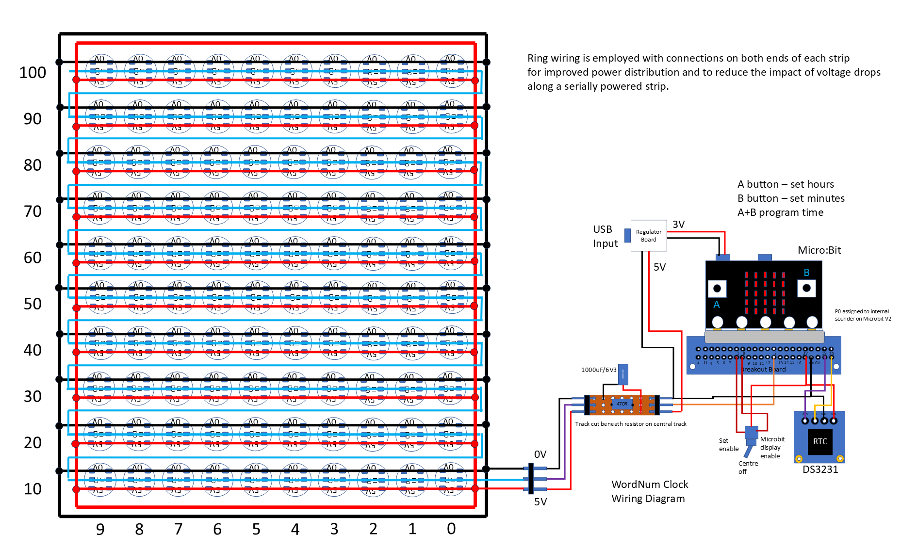
CircuitThe circuit elements consist of a Microbit V2, DS3231 RTC, Expansion Board, 100 Neopixel LED's, a switch and a RC network.
All the main elements are connected to the Expansion Board.
1: Microbit
2: RTC: VCC to 3V, GND to GND, SDA to pin 19 and SCL to pin 20.
3: Mode switch: COM to 3V, T1 to P1 (set enable) and T2 to P8 (display enable)
4: Microbit P2 via a 470R resistor connects to D1 of the first RGB LED.
5: The RGB LED's are supplied by 5V & 0V across which is connected a 1000uF electrolytic capacitior.
These elements are then mounted on a separate sheet of Acrylic which will be attached by screws to the back board.
Power is provided by a USB power adapter with a micro USB terminated cable.
Matrix AssemblyThe display consists of 100 addressable RGB LED's supplied on a strip.
The strip is cut into lengths of 10 LED's for a total of 10 strips.
Rather than connecting all three wires on each strip serially, I connected the supplies on a loop.
This means from a power perspective the 10 short strips powered at both ends present a parrallel and lower cumulative resistance reducing the effects of volt drops.
The loop is made from 8 x 250(L) x 1.6(dia) mm brass welding rods.
Four rods are cut to a lengths of ~ 18mm and soldered at the corners to form a connected square.
Four rods are cut to shorter lengths of ~ 19mm and soldered at the corners to form a connected square.
These two squares sit in two separate depressions in the outer part of the grid.
Designate each square frame to a supply polarity and mark part of the appropriate frame with coloured varnish/paint, permanent ink or a label.
Cut short lengths of ECW (Enamelled Copper Wire), and connect the supplies of the strips to the corresponding designated supply on the frame.
With a DMM on continuity/low resistance check the connectivity of the strip supply to the wire frame ensuring there are no shorts between the supplies.
Serially connect the DO to DI pins on each strip with ECW.
Connect the pins of three long jumpers to the strip at 5V, 0V and DI close to the corner.
Display AssemblyDetermine the exit point for the long jumpers and file or cut a slot in the grid perimeter.
With the Character Display face down, on top of this place the Diffuser and align the four corner (3mm), holes and repeat the process with the grid.
Feed 4 x M3 x 30mm plastic countersunk screws through the Acrylic retainer and through the holes of the Character Display, Diffuser and Grid sandwich and secure with 4 x M4 plastic nuts.
Align the LED Display on the grid with the first LED positioned over the lower right hand corner (O of the OCLOCK), of the Character Display.
The back panel requires 2 x 3mm holes which are countersunk on the reverse side these will align with two 3mm holes in a 3mm thick clear Acrylic rectangle of 120(L) x 60(W) mm, which are used to mount the circuit elements.
Into the 2 x 3mm holes in the back panel fit 2 x M3 x 20mm countersunk screws and secure with 2 x M3 nuts.
Secure the back panel to the back of the grid with 4 x M3 nuts.
Circuit Element PositioningThe circuit elements are mounted on a 3mm thick clear Acrylic rectangle of 120(L) x 60(W) mm, with 3mm holes drilled to align with the two M3 screws fitted in the back panel and held in place with 2 x M3 nuts.
The Expansion Board is mounted using plastic 2 x M4 x 10mm pan head screws, 2 x M4 washers and 2 x M4 nuts.
The RTC is mounted using 3 x M2 x 10mm pan head screws, 2 x 5mm threaded spacers and 3 x M2 nuts. This is orientated such that its battery is facing uppermost for easy replacement and the IO pins facing away from the USB connector.
The RC network is mounted on a small piece of strip board and 2 x 3pin straight header pins at the input and output.
The mode switch is mounted through a 6mm hole and an additional 6mm hole is placed next to the switch to enable the wires to be routed up and on to the Expansion Board.
The ends of the three wires from the display are vertically soldered to the output pins of the RC network.
I decided to wire wrap the remaining pins as they presented a lower profile that influenced the depth of the frame and which is a more robust and reliable connection than jumper wires. This also offers a tidy solution in a confined space compared to soldering.
Further details on wire wrapping can be found here: Allelcoelec.com which is one of many sources for information.
*No affiliation to the links provided and other sources may be used.
Before setting the clock ensure that the RTC has a working battery fitted to retain the time when/if power is removed.
The default time setting format is 24 hour mode.
The mode switch (centre off), has two functions time set and Microbit display.
With the switch in the centre position both the set mode and Microbit display are disabled.
In one position, set mode is enabled and the Microbit display is enabled during setting.
In the second position, set mode is disabled and the Microbit display is enabled for time display.
Being able to blank the Microbit display serves two purposes, 1: to save power, 2: as the Microbit is mounted at the back the Display will not be visible therefore it only needs to be visible when setting and verifiying the time.
Move the mode switch to the set time position a plus symbol will be shown on the display.
Press Button A for Hours. (0 to 23)*
Press Button B for Minutes. (0 to 59)*
*Each press incrementing the number to the maximum value and on the next press resetting to zero.
Press Buttons A & B together to set the time, the entered time values will be displayed.
Move the mode switch from the set position either to the centre or Microbit display enable.
With the mode switch in the centre position the Character Display will update after a short delay.
With the mode switch set for Microbit display enable the Microbit will show the time just before the Character Display updates.
At switch on or after setting.
If the clock has been previously set. after a short delay the time will be shown on the clock face.
Further details can be found here:


Comments
Please log in or sign up to comment.