


Hardware components | ||||||
 |
| × | 2 | |||
 |
| × | 1 | |||
| × | 1 | ||||
 |
| × | 1 | |||
 |
| × | 1 | |||
Software apps and online services | ||||||
 |
| |||||
 |
| |||||
 |
| |||||
Hand tools and fabrication machines | ||||||
 |
| |||||
| ||||||
| ||||||
The ARMADAS project was born with the need of creating an inexpensive alternative to PLCs ( Programmable Logic Controllers ) for factory data acquisition. PLCs have been the industrial standard for quite a while, but they are costly and require more expensive add-on modules.
The data acquired through the ARMADAS project are not mission critical readings. These readings are mainly used for OEE (Operating Equipment Effectiveness) which provide managerial staff information about the performance of the factory floor. Thus, the project was designed with minimal cost in mind, at the expense of reliability. But each board only costs around $5, which means that they can be replaced a hundred times over for the price of a PLC.
This project was tested and monitored for a couple of months at a factory floor. With the ARMADAS project, we hope to improve the energy management, remote monitoring and predictive maintenance of the factory.
Block Diagram and Project DescriptionThe types of inputs that had to be acquired from the factory floor were first identified.
- Digital Inputs - 12V/24V digital inputs from NPN or PNP sensors (proximity sensors etc.)
- Analog Inputs - Analog inputs from RTD sensors and 4-20ma sensors.
- Special Inputs - Values read using MODBUS protocol.
Then a method of transmitting the obtained values to a centralized server was developed. Two technologies were used.
- NRF24 - Radio Frequency based communication for areas of the factory with electrical interference that affects WiFi.
- MQTT over WiFi using ESP8266.
The block diagram illustrates all the key stages of the data acquisition process.
The central server was an AWS EC2 Instance, with a Mosquitto (MQTT) broker and a NodeJS script to display data on a web dashboard. Another application was developed using Visual Studio to visualize the data locally. (Data sent through RF was sent to a master RF device at the factory which had access to the internet).
PCB FabricationTwo PCBs were created for this project. One was designed around the popular ATmega328P-AU IC, and the other was for an ESP32-NodeMCU. Both of these PCBs have the following features.
- Internet connectivity - (using an external ESP8266 for the PCB with the ATmega IC) RF Connectivity for the ATmega board.
- 8x 4-20ma inputs using an analog multiplexer.
- Connectivity with up to 255 slave MODBUS devices over RS485.
- Two analog inputs for RTD sensors.
- 6 digital inputs for digital sensors through optocouplers (only 2 interrupt inputs for the atmega board)
- Additional ports to connect different peripherals through I2C, SPI or serial.
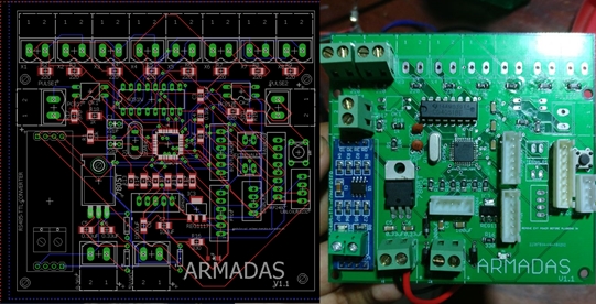
The PCB designed for the ATmega328P-AU is shown below.
The other PCB designed for the NodeMCU is shown below.
Board #1 -
- ATmega328P-AU
- 8 MHz Oscillator
- 4051N Analog Multiplexer IC
- 7085 5V Linear Regulator
- AMS1117 3.3V regulator
- 330Ohm Resistors - SMD 1206
- IN5041 Diode
- MAX485- RS485 Module
- NRF24 Transceiver
- ESP8266 module
- Wire Connectors
- Optocouplers
Board #2 -
- ESP12E NodeMCU
- 3.3V RS485 module
- LM2596 Buck Converter
- Optocouplers
- Wire Connectors
The programming was done using the Arduino Web Editor and Arduino IDE. **Codes are attached. (Special thanks to Doc Walker https://github.com/4-20ma ) for the ModbusMaster Arduino Library. The functions performed by the two boards are different to each other this they will be explained seperately.
1. ATmega328P-Based Board
This board was mainly used to acquire and transmit data over RF. One board was connected to a computer using a FTDI and was setup as the Master. All other boards were connected to different sensors in the factory floor and set up as slaves. At the request of the master, all other slaves would send the requested data. The master requests from each slave every 5 seconds. After the master receives the data it pushes it over serial to the computer, where a program written using Visual Studio displays it. This data is also pushed into a MQTT broker running at an AWS EC2 Instance.
Digital Inputs (pulse inputs) were obtained through an optocoupler since industrial signals run at 12-24V. 4-20ma inputs were obtained by sending the current through a 330 Ohm resistor and measuring the voltage. This was measured through a 4051N analog multiplexer to reduce the pin usage of the atmega. Some industrial devices connected at the factory are,
- Endress+Hauser Liquiline Sensor with 4-20macurrent outputs for pH, Chlorine concentration and Conductivity.
- Endress+Hauser Proline Promag – Magnetic FlowMeter – 4-20ma current output for flowrate and pulse output for totalizer.
- Schnieder Electric Energy Meter - kWh using MODBUS
When obtaining 4-20ma readings, it is necessary to obtain two known readings at the far ends of the range in order to determine the gradient and intercept of the voltage vs ADC value graph.
The above two pictures show the test bench prepared in order to evaluate the effectiveness of the project.
A SIM900 GSM module was connected to the master device in order to send requested readings via text.
2. NodeMCU Board
This board was connected to,
- Forbes Marshal FIT Steam Flowrate Sensor - Totalizer and Flowrate over MODBUS
- SET Power Meter - Three Phase Voltage, Current, Power Factor and kWh over MODBUS
The data gathered over MODBUS was directly sent to the MQTT broker.
The server backend consisted of a simple nodejs script to subscribe to different topics in the mqtt broker and visualize them.
It is apparent that Arduino based devices are a perfect alternative to PLCs for non mission critical tasks. If they are designed with appropriate filters and protection circuits, they can also be incorporated into critical tasks as well in the future. These devices were left to run in a factory environment for more than 2 months without running into any issues. The relative ease of programming using the Arduino Web Editor and the Arduino IDE, and the plethora of libraries and tutorials available made the development of this project a reality.


_3u05Tpwasz.png?auto=compress%2Cformat&w=40&h=40&fit=fillmax&bg=fff&dpr=2)
Comments
Please log in or sign up to comment.