


Hardware components | ||||||
_ztBMuBhMHo.jpg?auto=compress%2Cformat&w=48&h=48&fit=fill&bg=ffffff) |
| × | 1 | |||
| × | 1 | ||||
| × | 1 | ||||
 |
| × | 1 | |||
Software apps and online services | ||||||
 |
| |||||
Recently the corona virus outbreak has wreaked havoc in the whole world, the need and demand for medical instruments such as ventilators etc. has dramatically gone up, leading to their scarceness. So, there is a serious need for cheaper equipment and instruments. This DIY Heart Beat Sensor costs less than 15 dollars and can be effectively used for detecting heart beats and also plotting them in real time. The only hard work that needs to be done is to place your finger on the sensor for getting the readings.
Working :The working is basically governed by the differential opaqueness of any object(in this case the finger) in the presence of any fluid inside it(in this case blood). When the blood is pumped by the blood, there is more amount of blood in the blood vessels of the finger which makes it more opaque. When the blood retreats, there is less amount of blood in the blood vessels, the finger becomes less opaque. By measuring the opaqueness of the finger we can plot its curve which varies with the amount of blood in it. For taking this measurement, we use the IR emitter and Receiver.
The IR emitter throws light on the finger continuously, part of it is absorbed, part is reflected, some of it is transmitted,we need to plot the data with this very little amount of transmitted light( amount of light which passes through ). The detector on the other side of the finger detects this small amount of transmitted light. However, this intensity varies with the amount of blood in the finger so by plotting the values procured from the detector we get the real time plot of the heart beat of the person directly.
The output plot can be viewed on the serial plotter of the Arduino IDE.
Preciseness, filtering data for junk values :This involves removing error in the sensor values due to the ambient IR radiations, given off by many objects, even us!!. To do this the Arduino calculates the average junk reading beforehand, then removes this average junk reading to get the original, precise values. This is done by the following piece of code :
Now, calculating the sum of ambient junk readings 5 times so that we can eliminate them afterwards.
//For debugging
for(int i=0;i<5;i++)
     {
         reading = reading + analogRead(A0);
     }
 reading_final = (reading)/5;
Average junk reading is calculated.
     delay(100);
     Heart_rate = analogRead(A0)-reading_final;
Final reading value, much more precise. Then plotting of the variable Heart_Rate is done.
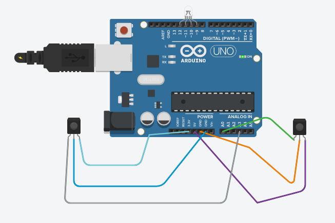
Setting up the sensor hardware :The sensor consists of an IR emitter and receiver. This is the schematics of the wiring that needs to be done.
The hardware setup will look like this in the end :
Here's a short video demonstrating the DIY sensor's working. The real time plot of my heart beat is being plotted. Just tap on this link to view it.
https://drive.google.com/file/d/1z1IdHuaXRA8mzHQuA-XZI3tvUSaRd30e/view?usp=drivesdsk.
******************************************************************************--------------------------------------------------------------------------------------
Here's a hack if you don't have the supplies needed :
An IR TV or any other electronic device's remote can also be used as the emitter with one of its buttons constantly pressed. And a light dependent resistor can be used for the receiver, just adjust its threshold for detecting IR radiations by looking at datasheets from the internet.
******************************************************************************--------------------------------------------------------------------------------------
I would love to hear from all those who tried this project. Suggestions for improvements and ideas for new projects are always welcome in the comments section.


Comments
Please log in or sign up to comment.