

Hardware components | ||||||
 |
| × | 2 | |||
 |
| × | 1 | |||
 |
| × | 1 | |||
 |
| × | 1 | |||
Software apps and online services | ||||||
| ||||||
IR Theremin Project gives options for users: "Options on what sound samples to link for each of the IR modules", and play them using a CLI interface from Processing.
First, take a look at the Demo Video of the project. (2 modules used).
For each video shot, different sound samples were assigned to the two modules that are connected to the PC via COM port.
Module topology, which enables the communication between multiple modules, is defined at [topology.h]. In the picture above,
Line 29 indicates: For module1 that is connected to the COM port, open a communication channel to module2's port1.
Line 30 indicates: For module2 that is connected to module 1, open a communication channel to module1's port4.
Line 45 indicates: Module2's port1 polarity is reversed. In this way, module1's RxD connects to module2's TxD with both modules facing upwards (the side of indication light).
For a tutorial on how to perform the basics, refer to:
https://hexabitz.com/docs/how-to/make-a-pre-built-array-topology-file/
The next step is to update the module firmware. Whenever a firmware is in the loop, we want each module to constantly detect whether there is an object within the distance threshold (In our case, used 200.0f, or 20cm).
A private variable called "sensor" and a method called "DetectedPing" was used in the project. The below photos show how the variables were used to determine output of the firmware, which is sent to PC via serial communication.
One thing to note here is that we used an additional functionality called "CODE_USER_MESSAGE_01" to send a message from module2 to module1. This way, when module1 detects an object within the distance threshold, the serial message "1\r\n" is sent to the PC && when module2 detects an object within the distance threshold, it passes a message to module1 to execute CODE_USER_MESSAGE_01.
In other words, to increase the number of modules used for IR Theremin and following the code setup, additional user messages (e.g. CODE_USER_MESSAGE_02, and so on), newly defined topology, and streaming tasks in "main.c" needs to be added.
For a tutorial on basic how-to, refer to the following link:
https://hexabitz.com/docs/code-overview-2/user-defined-messages/
After code setup is finished, follow this step (source: https://www.hackster.io/mahmoud-mardnly/air-piano-59d375)
"Click on Manage Project Items and add two targets (module1 and module2) if they're not already there. Choose each module from the dropdown menu and click on "Options for Target". Modify _module=1 in the "C/C++" tab into module number (1 to 7) and modify the name of the executable in the "Output" tab to match module number as well. Click on Batch Build >> Select All >> Rebuild."
Then, you can create .hex file from the build. Follow the instructions on:
in order to update .hex into your module firmware.
Phew, TY for your time on TL;TR! Just a little bit more!
Next is code in Processing IDE! Its job is to read the serial messages received from module1 and process the user-defined sound accordingly!
The lines underlined red is the declaration of the serial port within Processing IDE. The red box indicates two sound samples that are linked to the modules. For the case shown in the picture, module1 makes the "CrashCymbal.wav" sound and module2 makes the "TomTom.wav" sound.
void NewMainFunction() is the CLI display you will see once the program executes. Prior to doing so, make sure to take a look at "readme.txt" in the attachment file.
"atmakesound" variable lets users open or close the incoming serial messages and test software without serial communication. Menu 4 and 5 denoted as "Unknown Task" was created in order to further test the scalabilities of IR module in its communication with PC.
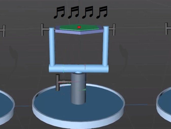
Next is the graphical model for a module stand that fits the project's use. Created in C4D, the video demonstrates
1. Adjusting the height of the module stand
2. Create angle variations for the module installed onto the module stand


Comments
Please log in or sign up to comment.