


Hardware components | ||||||
 |
| × | 1 | |||
_ztBMuBhMHo.jpg?auto=compress%2Cformat&w=48&h=48&fit=fill&bg=ffffff) |
| × | 1 | |||
Use your PC and Arduino as an oscilloscope!
Features- 1-100 kHz sampling rate (since v210603 full 100kS/s across all channels!)
- Up to eight channels simultaneously
- Basic trigger and cursor functions
- Basic recording to .csv functions
- Download the latest version (v210603)
- Extract to folder of your choice
- Upload included
at328p.inofile to your Arduino Uno/Nano or similar AT328P (Note: Please don't forget to reupload this if you're upgrading!) - Execute
ZS.exe, choose your COM-Port, channel config and sampling rate, and click Connect
- Windows 7 or newer operating system (Tested on Windows 7 and Windows 10 systems)
- Arduino Uno/Nano/other AT328P systems
- If your Arduino uses an FTDI USB/Serial Chip, you need to adjust latency from the default 16 ms to 1 ms for best performance. To do this, go to Device Manager, open COM port, go to Port Settings, click Advanced and adjust latency to 1 ms. USB/Serial chip CH340 does not have this issue, but has many COM communication errors at higher sampling rates.
- For higher sampling rates you may need to add a voltage follower to your signal, especially if your signal is high impedance, because the internal impedance of the Arduino will be very low at higher sampling rates. Otherwise, your signal can drop to zero volts. See Electrical Setup below for details on this.
- Since v210419, the included configuration file instructs the program to use the OpenGL renderer. Should it not start because of this, simply delete
ZS.cfg, as the program will then create a new one with the default settings, which uses Windows' built-in GDI system renderer instead. - Using the Export to PNG function requires
zlib.dllandlibpng.dllto be in the program's execution directory. - Recorded data/Exported diagrams are saved in program's execution directory.
- Diagram colors may be altered by editing
ZS.cfg, color values are saved in hex using RGBA format, e.g. red isff0000ff, blue isffffand yellow isffff00ff. DeletingZS.cfgwill force the program to load default values, and write a newZS.cfgupon program exit. ZS.cfguses a singleLF, not Windows'CRLFline-feeding, so use an editor that respects this convention (such as e.g. Notepad++) for editing this file. An editor that usesCRLFfor a new line will cause undefined behaviour.- Since v210603 the combined sampling rate of 100kHz can be guaranteed across all channel configurations (i.e. 100kHz for 1x, 12.5kHz for 8x channels) as long as your hardware supports it (FTDI vs. CH340 USB/RS232 chip issue)
v210603: Fixed and optimized AT328P's code, full 100kS/s rate across all channels and no "rate hole" at 30kHz, added FPS-cap in settings to reduce CPU-load
v210419: Added configuration file, German language support, OpenGL rendering, CSV recording
v200706: Renamed to ZaidaScope
v200704: Initial release
Electrical Setup (Optional)When using higher sampling rates, it may be necessary to add a voltage follower to the input signal, so as to not compromise the original measurement signal.
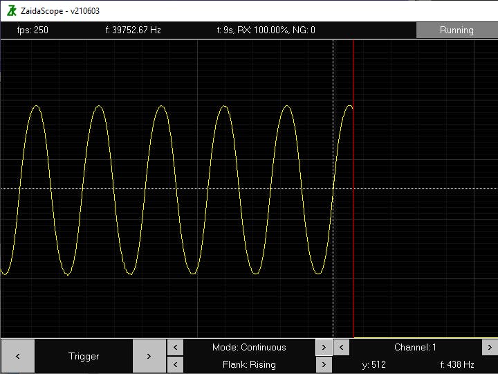
The screenshot above was created by reading my laptop's left channel audio output at a rate of 40 kHz while continously looping a generated 440 Hz sine wave using the program Audacity. This is how it the setup looks like:
The AT328P used on this board is an Arduino Pro Mini as well as a FTDI232 USB/Serial converter for communication, an SX1308 DC-DC step-up boost converter for powering the two LM324A op-amps, a number of diodes, resistors, capacitors and an LED.
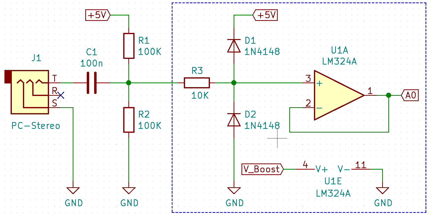
The simplified electric schematic for the above is as follows:
C1, R1 and R2 are required in order to get the audio signal centered around 2.5V, instead of the normal 0V.
On the PCB, the input signal is protected from undervoltage/overvoltage with D2 and D1. These ensure that the signal does not go under -0.5V or over 5.5V. In the case that this does happen, R3 prevents the current flowing through D2/D1 from getting too high.
Protecting the input signal from UV/OV is important, because the op-amp can push currents into the AT328P analog input at voltages higher than it can handle and damage it!
The LM324A is configured as voltage follower/in unity gain and thus provides the measurement signal with a higher impedance than a raw connection to the AT328P's analog input. In order to correctly mirror an input signal up to 5V, the op-amp must be powered by a voltage higher than 5V (V_Boost). The exact voltage depends on the type of op-amp used and also individually varies from op-amp to op-amp. An SX1308 DC-DC step-up module was used for this purpose, and in this case provides the LM324A with just about 6.35V, which also ensures that the op-amp's output never exceeds 5.1V.
WARNING: A higher voltage should only be used if measurement signals are never disconnected (since op-amps tend to saturate floating signals towards the voltage of their positive power supply).
Be advised that if the circuit's integrity is compromised, as well as when a measurement signal is floating/disconnected, the op-amp may output up to V_Boost into the AT328P and damage it!
It is therefore very risky to use more than 6.5V for any op-amp in the above circuit.
If you are uncertain of any of the above, do not attempt any of it.
BackgroundZaidaScope is an open-source software that was born out of the libraries created for a commercial client's request for a low-cost alternative to using traditional and expensive aftermarket DAQ hard- and software to monitor analog input channels on a PC.
The AT328P was chosen, as its low cost, abundance, bit-depth and sampling rate were all deemed to be sufficient for the task.
Visit our website for contact details if you require a similar custom solution.
LicenseCopyright (C) 2019-2020 ZaidaTek and Andreas Riebesehl
This work is licensed under: Creative Commons Attribution-NoDerivatives 4.0 International Public License
For full license text, please visit: https://creativecommons.org/licenses/by-nd/4.0/legalcode


Comments
Please log in or sign up to comment.