I am keen on building my own Electronics since this enables me to understand how things work as well as get to tailor them according to my own needs. Therefore I encourage learning by doing as a means of discovery and acquisition of both knowledge and skills. And what better way to understand how electronic components really work in a circuit than by building your very first circuit.
As a matter of fact, one of the main reasons why building electronics seems cumbersome for beginners is the fact that it requires not only knowledge and skills, but also buying a lot of hardware and tools. Therefore, My first circuit is a plug-and-play electronics kit that enables experimentation without soldering.
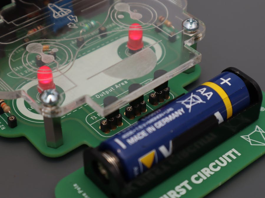
OverviewMy first circuit is a fun and easy to assemble Do it Yourself kit that does not require soldering. It combines some of the most common electronic components (such as LEDs, resistors, capacitors, transistors etc.) with others that are rather interesting like the photo-resistor.
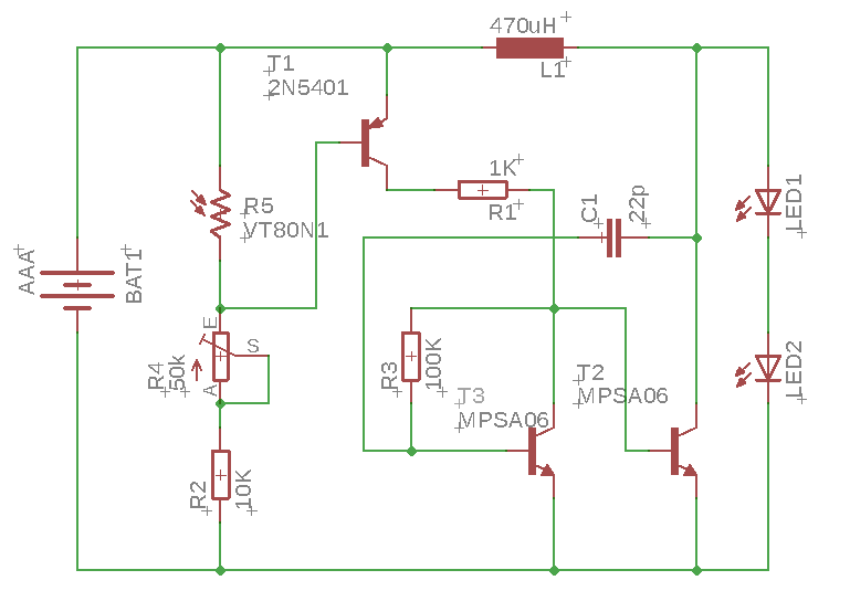
How it worksFrom a functional point of view it is a so-called joule thief or vampire torch that only actives in the dark. Specifically, LEDs need 3V to light up but the circuit is powered using only a 1.5V battery. However, when the photo-resistor detects low levels of light intensity the LEDs light up. How is that possible? The circuit has a voltage booster area that increases the voltage to nearly 6V so that it can power both LEDs in series. It does it through an oscillatory behaviour that fills the capacitor with voltage. Further, when the capacitor is charged the transistor comes into play as it releases all the voltage to the LEDs all at once. This process is iterated until the battery is fully discharged. This also means that the lights are not on all the time, but it all happens so fast that it is not visible to the naked eye.
So, it can use nearly all of the energy in a single-cell electric battery, even far below the voltage where other circuits consider the battery fully discharged (or "dead").
And, of course, it can serve you as a night-light.
AssemblyLet's see what are the steps to build your very first circuit.
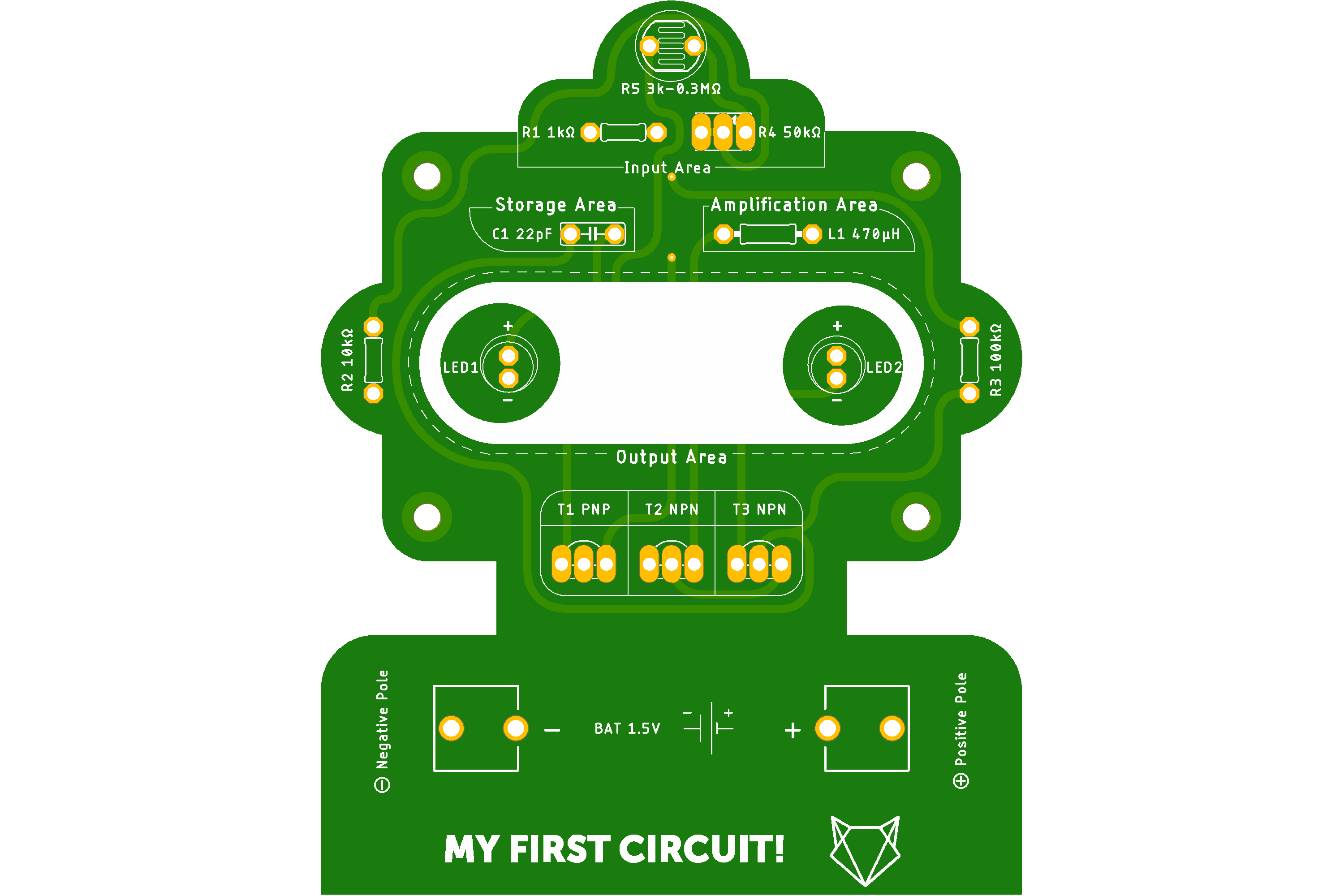
Step oneGet to know your components. For instance you can tag each component according to its name and symbol on the PCB. You can also use the BOM received in the kit, that includes a brief description of each electronic component.
Make sure that you have properly identified the resistors and the transistors. If you don't have a multimeter to determine the value of the resistors, you can use the resistor colour code via a simple search on the internet.
Step twoIn order to build the circuit, you will have to mount the components in the pins that are already soldered on the PCB. Mounting components such as transistors, capacitors, photoresistors, potentiometer or LEDs is pretty straight-forward, as you simply push them into the pin sockets.
Do note that when connecting the LEDs you have to account for the polarity, that is be sure to follow the "+" and "-" marked on the PCB. Oneway to identify the positive and the negative leads of the LED, the positive one is usually the longer lead. However, if the leads are equal in length or just to be sure, you can guide yourself taking a look at the metal plate inside the LED - the smaller plate is the positive lead, while the larger plate is the negative lead.
As for mounting the resistors and the inductors, you will have to bend their leads so that they will fit the the distance between their respective pin sockets.
Similarly, after you have connected all the electronic components mount the AA battery, taking into account the polarity.
Step threeTest the functionality of the circuit by covering the photoresistor. If you have connected the components correctly the LEDs should light.
If the LEDs are notturned on, you may first check whether the components are mounted according to the schematics. Anotherdebugging suggestionis to verify that all the leads of the components are mounted in the pin sockets.
Otherwise,you should lookfor the component that iscausing the circuit to malfunction. For instance, start with the photoresistor - if you remove it, do the LEDs light? If they do, then you have successfully identified your culprit.
You might also want to check the potentiometer, as it is used to adjust the sensibility of the photoresistor - if it is set too low, then you will not see the LEDs light.
Step fourOnce you have determined that the circuit is functional, go ahead and finish the assembly by mounting the plexiglass cover.
You will need a cross screwdriver. First attach the screwed spacer sleeves on the top face of the PCB. Then put the plexiglass cover on top the spacer sleeves and fasten it with the remaining screws.
Video walk-through


Comments
Please log in or sign up to comment.