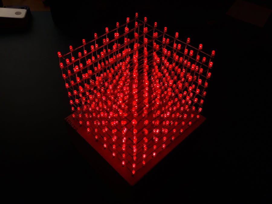
by the work of Chr
Preparation:test all 512 LEDs (and additional 50 spare ones if some get damaged while soldering) to find all the malfunctioning ones. Let them run for at least 4 hours.
make symmetrical holes in a wooden/plastic box and place the LEDs there to make a 8x8 grid.
Step 1:bend the cathode legs of all LEDs. Solder one cathode leg to the next cathode leg. If necessary, use a copper wire to connect the LEDs. Do not overheat the them (solder as quickly as possible). When the whole layer is done, check with the multimeter if the LEDs still work.
when all 8 layers are done, place one layer with the LEDs facing to the table. In the finished cube, that will be the top layer.
Start making a cube: connect the anode legs of the bottom layer with the anode legs of the next layer. You might need to bend these legs at the end to get around the body of the LED above.
The PCB design and the circuit you can find on my CircuitMaker page:https://circuitmaker.com/Projects/Details/Stefan-Grndinger/8x8x8-LED-Cube-Control-Board
I ordered the PCB from JLCPCB.
The PCB is designed to plug in an Arduino Nano. However it can also work with other controllers like STM32.
Connect the anodes with the PCB using stranded wires and add heat-shrink tubes.
All bits are shifted into the flip-flops via SPI communication.
You can download a test code from my Github repository and run it.


Comments
Please log in or sign up to comment.