Hackster is hosting Hackster Holidays, Ep. 7: Livestream & Giveaway Drawing. Watch previous episodes or stream live on Friday!Stream Hackster Holidays, Ep. 7 on Friday!
Mark Easleyjcollins
Published

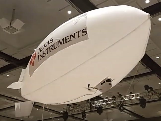
Blimp DIY

Build your own DIY remote-controlled blimp for flying for sport or for commercial use.

AdvancedFull instructions provided6 hours5,035
Blimp DIY

Things used in this project

Story

Read more

Code

Blimp controller code

C#
Energia code for the blimp controller
#include <SPI.h>
#include <AIR430BoostFCC.h>
#include "Energia.h"
#include "Screen_HX8353E.h"
Screen_HX8353E myScreen;

const int joyX = A5;
const int joyY = A3;
uint16_t colour = redColour;
#define ANALOG_HALFVCC_INPUT A11
// -----------------------------------------------------------------------------
/**
 *  Global data
 */

// Data to write to radio TX FIFO (60 bytes MAX.)
//unsigned char txData[6] = { 'S', '\0', '\0', '\0', '\0', '\0' };

struct sPacket
{
  uint8_t from;
  int rud;
  int Dir;
  int lPWM;
  int rPWM;
  int motor;
};

struct sPacket txData;

struct rPacket
{
  uint8_t from;
  int vcc;
};

struct rPacket rxData;

int analogTmp = 0; //temporary variable to store 
int throttle, direct = 0; //throttle (Y axis) and direction (X axis) 

int leftMotor,leftMotorScaled = 0; //left Motor helper variables
float leftMotorScale = 0;

int rightMotor,rightMotorScaled = 0; //right Motor helper variables
float rightMotorScale = 0;

float maxMotorScale = 0; //holds the mixed output scaling factor

int deadZone = 10; //jostick dead zone 

int btn1 = 0;
int btn2 = 0;
int btn3 = 0;
int rud;
int rssi = 0;

int getVCC() {
  // start with the 1.5V internal reference
  analogReference(INTERNAL1V5);
  int data = analogRead(ANALOG_HALFVCC_INPUT);
  // if overflow, VCC is > 3V, switch to the 2.5V reference
  if (data==0xfff) {
    analogReference(INTERNAL2V5);
    data = (int)map(analogRead(ANALOG_HALFVCC_INPUT), 0, 4096, 0, 5000);
  } else {
    data = (int)map(data, 0, 4096, 0, 3000);
  }
  analogReference(DEFAULT);
  return data;  
}

//-----------------------------------------------------------------------------
// Debug print functions

void printTxData()
{
  Serial.print("Rud, Dir, leftPWM, rightPWM, Payl:  ");
  Serial.print(txData.rud); 
  Serial.print(", ");
  Serial.print(txData.Dir);
  Serial.print(", ");
  Serial.print(txData.lPWM);
  Serial.print(", ");
  Serial.print(txData.rPWM);
  Serial.print(", ");
  Serial.println(txData.motor);
}

void printRxData()
{
  Serial.print("RxVcc, rssi:  ");
  Serial.print(rxData.vcc); 
  Serial.print(", ");
  Serial.println(rssi);
}

// -----------------------------------------------------------------------------
// Main example

void setup()
{
  Serial.begin(19200);
  myScreen.begin();
  
  pinMode(33, INPUT_PULLUP);  //configure motor tilt switches
  pinMode(32, INPUT_PULLUP);
  pinMode(P2_1, INPUT_PULLUP); //Pullup for LP S1 and S2
  pinMode(P1_1, INPUT_PULLUP);
  pinMode(5, INPUT_PULLUP);   //Pullup for thumbstick button (payload)
  
  // The radio library uses the SPI library internally, this call initializes
  // SPI/CSn and GDO0 lines. Also setup initial address, channel, and TX power.
  Radio.begin(0x04, CHANNEL_2, POWER_MAX);
  
  delay(100);
  
  txData.from = 0x04;
}

void loop()
{
   //aquire the analog input for Y  and rescale the 0..1023 range to -255..255 range
  analogTmp = analogRead(joyY);
  throttle = -(2048-analogTmp)/8;

  delayMicroseconds(100);
  //...and  the same for X axis
  analogTmp = analogRead(joyX);
  direct = -(2048-analogTmp)/8;
  rud = map(analogTmp, 0,4096,25,155);
  
  //mix throttle and direction
  if(throttle >= -8){
    leftMotor = throttle+direct;
    rightMotor = throttle-direct;
  }
  else{
    leftMotor = throttle-direct;
    rightMotor = throttle+direct;
  }

  //calculate the scale of the results in comparision base 8 bit PWM resolution
  leftMotorScale =  leftMotor/255.0;
  leftMotorScale = abs(leftMotorScale);
  rightMotorScale =  rightMotor/255.0;
  rightMotorScale = abs(rightMotorScale);

  //choose the max scale value if it is above 1
  maxMotorScale = max(leftMotorScale,rightMotorScale);
  maxMotorScale = max(1,maxMotorScale);

  //and apply it to the mixed values
  leftMotorScaled = constrain(leftMotor/maxMotorScale,-255,255);
  rightMotorScaled = constrain(rightMotor/maxMotorScale,-255,255);
  
    //Read button values for motor tilt and payload dropper
    btn1 = digitalRead(32);   //read push button to move motor angle
    btn2 = digitalRead(33);   //read push button to move motor angle
    btn3 = digitalRead(5);    //read push button to activate payload 
    
    if(btn2 == 0){    //increase motor angle
      txData.motor = 1;
    }
    else if(btn1 == 0){  //decrease motor angle
      txData.motor = 2;
    }
    else if(btn3 == 0){   //payload dropper
      txData.motor = 3;
    }
    else{
      txData.motor = 0;
    }

  // Store data in array for transmission
    txData.rud = rud;    
    txData.lPWM = leftMotorScaled;
    txData.rPWM = rightMotorScaled;
    
    // Load the txData into the radio TX FIFO and transmit it to the broadcast
    // address.
    printTxData();                    // TX debug information 
    Radio.transmit(0x03, (unsigned char*)&txData, sizeof(txData));
    
    while (Radio.busy());
    
    if (Radio.receiverOn((unsigned char*)&rxData, sizeof(rxData), 1000) > 0)
    {
      if(rxData.from == 0x03)
      {
        int data = getVCC();
        rssi = Radio.getRssi();
        printRxData();
        myScreen.gText(0, myScreen.screenSizeY()-myScreen.fontSizeY(),
                     "Left=" + i32toa((int16_t)leftMotorScaled, 1, 0, 4),
                     colour);
        myScreen.gText(0, myScreen.screenSizeY()-2*myScreen.fontSizeY(),
                     "Right=" + i32toa((int16_t)rightMotorScaled, 1, 0, 4),
                     colour);
        myScreen.gText(0, myScreen.screenSizeY()-3*myScreen.fontSizeY(),
                     "TX Batt= " + i32toa((int16_t)data, 1000, 3, 5) + "V",
                     colour);
        myScreen.gText(0, myScreen.screenSizeY()-4*myScreen.fontSizeY(),
                     "RX Batt= " + i32toa((int16_t)rxData.vcc, 1000, 3, 5) + "V" ,
                     colour);
        myScreen.gText(0, myScreen.screenSizeY()-5*myScreen.fontSizeY(),
                     "RSSI=" + i32toa((int16_t)rssi, 1, 0, 5) + "dBm",
                     colour);
      }
    }
    
  //To do: throttle change limiting, to avoid radical changes of direction for large DC motors

  delay(10);

}

Blimp receiver code

C#
Energia code for the blimp receiver and motor control
#include <SPI.h>
#include <AIR430BoostFCC.h>
#include <Servo.h> 

// -----------------------------------------------------------------------------
/**
 *  Global data
 */

Servo motor, rudder, payload;  //initialize servo objects
int pos;          //servo angle integer
int deadZone = 10; //jostick dead zone 

// Data to read from radio RX FIFO (60 bytes MAX.)
struct sPacket
{
  uint8_t from;
  int rud;
  int Dir;
  int lPWM;
  int rPWM;
  int motor;
};

struct sPacket rxData;

struct tPacket
{
  uint8_t from;
  int vcc;
};

struct tPacket txData;

// -----------------------------------------------------------------------------
// Debug print functions

#define ANALOG_HALFVCC_INPUT 11

// returns VCC in millivolts
int getVCC() {
  // start with the 1.5V internal reference
  analogReference(INTERNAL1V5);
  int data = analogRead(ANALOG_HALFVCC_INPUT);
  // if overflow, VCC is > 3V, switch to the 2.5V reference
  if (data==0x3ff) {
    analogReference(INTERNAL2V5);
    data = (int)map(analogRead(ANALOG_HALFVCC_INPUT), 0, 1023, 0, 5000);
  } else {
    data = (int)map(data, 0, 1023, 0, 5000);
  }
  analogReference(DEFAULT);
  return data;  
}

void printRxData () 
{
   Serial.print(rxData.rud);
   Serial.print("| ");
   Serial.print(rxData.Dir);
   Serial.print("| ");
   Serial.print(rxData.lPWM);
   Serial.print("| ");
   Serial.print(rxData.rPWM);
   Serial.print("| ");
   Serial.println(rxData.motor);
}

// -----------------------------------------------------------------------------
// Main example

void setup()
{
  // The radio library uses the SPI library internally, this call initializes
  // SPI/CSn and GDO0 lines. Also setup initial address, channel, and TX power.
  rudder.attach(11);   //Rudder servo initialization (header closest to payload servo)
  rudder.write(90);
  delay(510);
  rudder.detach();
  motor.attach(2);   //Motor servo initialization(header closest to pin 1)
  motor.write(90);
  delay(510);
  motor.detach();
  payload.attach(5);   //Payload servo initialization (Middle header)
  payload.write(0);
  delay(1000);
  payload.detach();
  
  Radio.begin(0x03, CHANNEL_2, POWER_MAX);
  txData.from = 0x03;
  
  analogFrequency(15000);   //set analog write frequency

  // Setup serial for debug printing.
//  Serial.begin(9600);
//  Serial.println("Receiver is listening...");
  

  /**
   *  Setup LED for example demonstration purposes.
   *
   *  Note: Set radio first to ensure that GDO2 line isn't being driven by the 
   *  MCU as it is an output from the radio.
   */
     pinMode(9, OUTPUT);   //Left motor neg
     pinMode(4, OUTPUT);  //Left motor pos
     pinMode(12, OUTPUT);   //Right motor pos
     pinMode(13, OUTPUT);   //Right motor neg
     
     digitalWrite(9, 0);    
     digitalWrite(4, 0);
     digitalWrite(12, 0);     
     digitalWrite(13, 0);   
}

void loop()
{
  
  // Turn on the receiver and listen for incoming data. Timeout after 1 seconds.
  // The receiverOn() method returns the number of bytes copied to rxData.
  txData.vcc = getVCC();
  
  Radio.transmit(0x04, (unsigned char*)&txData, sizeof(txData));
  
  while (Radio.busy());
  
  if (Radio.receiverOn((unsigned char*)&rxData, sizeof(rxData), 100) > 0)
  {
    if(rxData.from == 0x04)
    {
//      printRxData();     // RX debug information 
      
     //apply the results to appropriate uC PWM outputs for the LEFT motor:
      if(abs(rxData.lPWM)>deadZone)
      {
    
        if (rxData.lPWM > 0)
        {
          digitalWrite(9, LOW);    
          analogWrite(4, abs(rxData.lPWM));  
        }
        else 
        {
          digitalWrite(4, LOW);
          analogWrite(9, abs(rxData.lPWM));         
        }
      }  
      else 
      {
      digitalWrite(9, 0);    
      digitalWrite(4, 0); 
      } 
    
      //apply the results to appropriate uC PWM outputs for the RIGHT motor:  
      if(abs(rxData.rPWM)>deadZone)
      {
    
        if (rxData.rPWM > 0)
        {
           digitalWrite(13, LOW);   
           analogWrite(12, abs(rxData.rPWM));
        }
        else 
        {
           digitalWrite(12, LOW);   
           analogWrite(13, abs(rxData.rPWM));
        }
      }  
      else 
      {
      digitalWrite(12, 0);     
      digitalWrite(13, 0); 
      }

      rudder.attach(11);   //Rudder servo mix for turning
      rudder.write(rxData.rud);
      delay(80);
      rudder.detach();
            
      //Motor tilt and Payload  
        motor.attach(2);
        pos = motor.read();
        motor.detach();
        switch(rxData.motor) {
         case 1:
           pos += 2;    //increment angle by 2 degrees
           if (pos > 180){pos = 180;}
           motor.attach(2);   //Motor servo
           motor.write(pos);  //write motor to angle
           delay(4);         //wait for servo to get to new angle
           motor.detach();    //detach servo
           break;
        case 2:
           pos -= 2;     //decrement angle by 2 degrees
           if (pos < 0){pos = 0;}
           motor.attach(2);   //Motor servo
           motor.write(pos);  //write motor to angle
           delay(4);         //wait for servo to get to new angle
           motor.detach();    //detach servo
           break;
        case 3:
           payload.attach(5);   //Payload servo
           payload.write(180);   //move payload arm 180 degrees to drop coupons
           delay(950);           //wait for arm to reach position and hold
           payload.write(0);     //move payload arm back to neutral point
           delay(950);
           payload.detach();
           break;
        
        default:    
           break;
        }
     }
  }
}

Credits

Mark Easley
65 projects • 138 followers
Texas Instruments LaunchPad SW Engineer
jcollins
1 project • 0 followers
Thanks to Josh Collins.

Comments