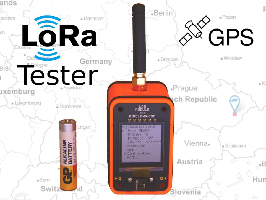
Ultimate palm-size LoRa tester that can configure every LoRa parameter you would think of.
Open source code, worldwide frequencies, datarates including Class C and periodic sending support. With GPS Module you can send location directly to the TTN Mapper service which will measure also the LoRa signal strength.
For Basic LoRa Tester, you will need:
ORindividual modules:
For Advanced LoRa Tester with GPS,you will need:
OR individual modules:
The communication keys can be set over USB virtual serial port by using simple AT commands. More information in Step 3 and HARDWARIO developer docs. For example:
AT$APPSKEY=BF22C15EB89237A65DAABB05B2C91EB4- Short press of left or right button moves UP and DOWN.
- Long press of right button confirms the item (ENTER).
- Long press of the left button returns from submenu without applying changes (ESC).
Send - Sends manually a single packet with configured parameters
TX Data - Select packet payload from 1 byte up to 230 bytes. By selecting option "GPS, Temp" the device will send its location, altitude and temperature
TX Period - Automatic sending of data from 5 seconds up to 60 minutes
GPS Info - If you connect GPS Module, then in this menu you see details and whether the GPS is fixed.
Mode - Choose ABP or OTAA LoRa Mode
Join - Transmit the Join packet if you select OTAA
Confirmation - Option to send packets that needs to be acknowledged by the LoRa gateway
Port - Transmit port selection
Band - Select the proper frequency and location. Options are:
- AS923
- AU915
- EU868
- KR920
- IN865
- US915
Datarate - this menu can be different based on selected band. Options are:
- SF12/125kHz
- SF11/125kHz
- SF10/125kHz
- SF9/125kHz
- SF8/125kHz
- SF7/125kHz
- SF7/250kHz
- FSK 50kbit
Network - Public or Private LoRa network
Class - Class A (listen for while after transmitting) or Class C (listen all the time)
Received - Counter of received packets
RX - Displays first few bytes of received message
Battery - Battery voltage
Sleep - You can turn off the device. Display turns off, LoRa is set to Class A and GPS is turned off. Use the long press of left button to wake-up again
Step 1: Build HardwareStack the HARDWARIO IoT Kit modules on top of each other. Start with a Mini Battery Module and build other modules on top of it. It does not matter on the order which you stack modules on top. HARDWARIO IoT Kit is designed to connect the modules the way you like.
Download HARDWARIO Playground multiplatform GUI tool to your computer. This tool can flash firmware. It also contains other features like MQTT broker and Node-RED with dasboard but we will not use that in this project.
- Connect Core Module to your PC and wait until the FTDI driver is installed
- Run the HARDWARIO Playground
Go to the Firmware tab and write "lora-tester" to the firmware textbox to filter firmwares, choose bcf-lora-tester-lcd-gps-ttnmapper firmware.
- Choose the correct serial COM port and press "FLASH FIRMWARE" button
- After flashing, the Core Module will turn on red LED for 2 seconds and will display a menu on the LCD Module.
- See troubleshooting section or visit HARDWARIO forum if something goes wrong
Here I explain how to set-up the tester with The Things Network.
Create an account on The Things Network and create a new application.
Go to the newly created Application, open Devices and click Register Device
Fill in Device ID which is just naming your device. Then in Device EUI click on the icon so the text "this filed will be generated" will appear.
Now you will need copy these three keys one after another to LoRa Tester. You do this by connecting Core Module over USB to your computer and use HTerm, picocom or Arduino Serial Monitor software. Make sure you have the right CR+LF line ending and 115200 baud!
You should write these three keys to the LoRa Tester (ok, two EUIs and single key).
You type just the AT commands and you get the OK replies from the LoRa Tester.
AT
OK
AT$DEVEUI=002A99DD6DBC8C9A
OK
AT$APPEUI=70B3D57ED001013D
OK
AT$APPKEY=02768539CFA12A8C174EF19FB2739DEA
OK
Complete guide with recommended console programs are on developers site.
You can now disconnect the LoRa Tester from the USB.
Step 4: Joining the LoRa NetworkNow in the LoRa Tester menu choose MODE item and set it to OTAA.
Then in the menu choose Join command and wait 5 seconds for response. If you get ERROR, make sure you have good signal from your gateway, try to go outside.
If you get JOINED response, then the LoRa Tester has joined the network sucessfully.
Now you can try to send first packet, use the first item in the menu: SEND
Step 5: Integration with TTN MapperThere's a custom TTN decoder javascript in app/ttn_decoder.js that converts the bytes to the TTN Mapper data format.
Copy just the Decoder function to the Payload Formats and save the changes
Now add the TTN Mapper in integrations and fill just the email and Experiment name. Write down this experiment name, later you will need it!
In the LoRa Tester menu set TX Data option to GPS, Temp. You need to wait until GPS is fixed. When the GPS info menu item starts to display your coordinates, you can move to the next step.
Send the packet!
In the data you will see the decoded packet with latitude and longitude.
Now go to the website, fill in your experiment name in the URL!
https://ttnmapper.org/experiments/map.php?name= <name_of_your_experiment>You can also list all the experiments.
And you should see your position


Comments
Please log in or sign up to comment.