


Hardware components | ||||||
 |
| × | 1 | |||
Software apps and online services | ||||||
 |
| |||||
 | ||||||
When do I need to empty the dehumidifier bucket? Sure it beeps and the little LED blinks constantly when the bucket is full. That is just great if I were sitting in the basement all day. But who wants to sit in a dark basement all day. The solution is to enable the dehumidifier to Tweet when its bucket is full. Thanks to lots of help from SparkFun and ThingSpeak this is actually a pretty easy project.
WARNING: before taking panels off any electrical device make sure to unplug the device from the electrical outlet. Even when the power cord is unplugged there can still be powerful electrical charges stored in the power supply or other parts of the unit. Stay away from the power supply! Cover the exposed metal surfaces of your tools with electrical tape. Never work alone! Familiarize yourself with all the electrical components in the unit before you begin. As always there is lots of great documentation online for almost all models ever made.
First Step: Find the water level switchRemoving the water collection bucket reveals a small switch at the back of the cavity. Pushing the switch several times and watching the control panel bucket full LED proves this is the correct switch.
Taking the back panel off exposes a small white enclosure housing the switch.
From the back the white enclosure is easily accessible and doesn’t require any additional dismantling of the unit. Which makes accessing this switch fairly low risk. The enclosure was held in place using a single screw and some plastic tabs, which I broke, Dooooh!. But the broken tabs do not seem to interfere with the operation of the unit, thankfully!
Found this extremely helpful diagram inside the back cover:
The water level switch is top center of the diagram. These switches have a normally open side and a normally closed side. Depending on which side you connect to, you check for the opposite condition. The diagram shows the dehumidifier is monitoring the normally open side and therefore checks for a switch closed condition to report that the bucket is full.
Next Step: Get inside to the switchInside the enclosure is the contact switch. The switch is spring loaded with a contact for the normally open position and the normally closed position and a common connection completing the circuit. Most applications only utilize one side of the switch leaving the other side available obviously for hackers.
Here the blue wire is connected to the common side and the red wire is connected to the normally open side of the switch. The normally closed side is available to me! All I have to do is connect a wire to the remaining unused connector and splice a wire into the blue wire for the common connection.
Due to the tight space in the enclosure I decided to drill two holes for my wires to exit out of the enclosure in line with the switch’s connectors. This allowed me to use a straight connector I had on hand.
Next Step: Make connection to the switch.Here my hacked wires are exiting the reinstalled enclosure. It doesn’t matter which wire is connected to which side, common or NC, of the switch since the switch just breaks the circuit when the switch is closed. But it is nice to have a color for each connection.
I just estimated the point where the wires would exit the housing. Then drilled two holes in the case. The top hole will have a screw inserted from the inside and protruding on the outside. This will be where I mount my project board.
The lower hole is where the wires will pass through to the exterior. I used a slightly larger bit than necessary to make sure the wire insulation is not damaged as it is inserted.
The holes were pretty easy to drill. However the plastic cover is not designed to take a lot of pressure. So I supported the case side on my work bench while drilling to prevent cracking.
Next Step: Put the case back together and test.With the cover reinstalled and the wires exiting the case it looks pretty good for guess work.
Now to test out the hack so far to make sure everything is working before moving on to the project board. It is better to fix it now then have another unknown variable to trouble shoot when testing the rest of the build.
The easiest way to test this is to use a multi meter and check for continuity. So here is the set up.
With the bucket inserted and empty, the switch is closed. Connect the multi meter leads to the newly installed red and green wires and set the multi meter to continuity. I highlighted the needle with a red line to make it more visible.
With the configuration listed above the meter shows infinite resistance or an open circuit. Since my wires are connected to the NC, normally closed, side of the switch this is as expected.
So far so good…
Next with the bucket removed the switch is open. Now the multi meter shows Zero resistance or closed circuit. This is the expected results so the hack is working!
Now we need a circuit to detect these conditions and then take action to tweet for help.
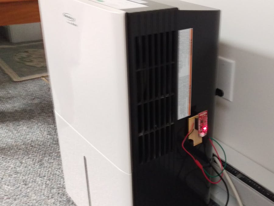
Next Step: The board buildThanks to the SparkFun Esp8266 Thing the build is pretty much done for me. All I need to do is connect my hacked wires from the dehumidifier to the Thing’s Ground and Digital pin 12.
OK I used a broken Radio Shack 2760150 board for this build but I only needed a couple of connections. Also note no external resister is used because I set pin 12 to INPUT_PULLUP. Which activates an internal resister.
Next Step: Setup ThingSpeakThingSpeak.com provides the connectivity to talk to services like Twitter. They provide all the heavy lifting in the way of API's. All my sketch does is send my tweet to their API and they take it from there. They also provide very good documentation that walks you thorough the process. I will not attempt to replicate their documentation as I could not even get close to the quality they provide. But the basic concepts are:
Setup a ThingSpeak account.
Create a channel,
Choose an action, I chose ThingTweet
get an API Key that identifies you to the function you want to run.
install the ThingSpeak library for Arduino
Add some code to your sketch to call the ThingSpeak API
Done!
Next Step: Write the sketch.Writing this sketch was super easy. Thanks to the Esp8266WiFi library and the ThingSpeak ThingTweet app.
The program logic flow is
1. Check the pin connected to the contact switch.
2. if the contact pin has changed since the last time it was checked then get ready to tweet
3. if the pin = Low then the bucket if full so tweet the full bucket message
else tweet the empty bucket message
Sleep for a while and repeat from the top.
The complete sketch is in the code section.
Next Step: Check Twitter.You have to have a twitter account to be able to talk to twitter. It is also required when setting up your ThingSpeak channel. Once that is done you simply check the twitter account and see the results below..
Success!!
Future updates- Add humidity sensor or hack the one on the dehumidifier and then tweet humidity or store humidity data online
- Get rid of external power supply by tapping into the units internal power
- Add a list of bucket full/bucket empty tweets and select them at random to make it more interesting
- Add relay to power a pump to automatically empty the bucket for me.
- Suggestions?


_3u05Tpwasz.png?auto=compress%2Cformat&w=40&h=40&fit=fillmax&bg=fff&dpr=2)

Comments
Please log in or sign up to comment.