Watch the video first -
Have you ever Made a Project like an “LDR x Arduino UNO Automatic Light” or similar which only uses 2-3 Digital I/O ports of your 32 Pin Microcontroller?
It’s okay if you’re just doing some prototyping work but what if you want to finalize or produce that prototype as a product, not as a project. One alternative is to use a smaller and cheaper Microcontroller which costs less and can be implemented easily in any low requirement project.
Microchip has a line of microcontrollers called “ATTINY AVR” which are little microcontrollers that can do a lot of the work that an Arduino does in a much more compact form.
In this post, I’ll be showing you guys how exactly you can use an Attiny84 as a LOWKEY Arduino replacement for Low Spec Projects.
Attiny84 is an 8 Bit Microcontroller based on AVR® RISC with 8KB Program Memory and can be operated between 1.8 to 5.5 Volts.
Check its datasheet for more info about Peripherals and stuff.
https://www.microchip.com/wwwproducts/en/ATtiny84
But why I choose Attiny84 over the very popular 8-pin ATtiny85?
The reason is I/O and cost, for few more cents we are getting more I/O pins
Attiny85- 6 I/O pins for 1$ (80 cents if buy in bulk)
Attiny84- 12 I/O pins for 1.2$ (1$ if buy in bulk)
I got myself 10 Attiny84 in SOIC14 Package but there’s a DIP14 version available which is breadboard friendly.
The Attiny84 has a total of 14 Pins, two of them are VCC and GND and rest are I/O pins which can be used to read/write XYZ stuff.
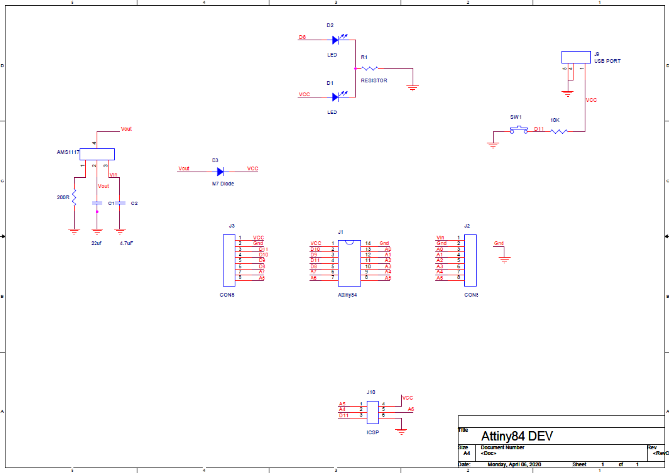
After mapping its Pinout, I designed a breakout board for it in ORCAD CADENCE and send its Gerber files to JLCPCB.
JLCPCB is one of the best PCB manufacturers out there in the market,
they offer great PCB service with less price, 5pcbs for just 2$,
I got myself 10pcbs with black solder mask because black is cool.
after receiving the PCB, I started assembling stuff.
Components used in this project
- Attiny84 SOIC14 x1
- AMS1117 3.3V x1
- 4.7uf SMD 0805 x1
- 100uf SMD 0805 x1
- 200Ohms 0805 x1
- 1K 0603 x2
- M7 Diode x1
- SMD push button
- Custom PCB
- LED 0603 x2
- Male Header pins
- USB micro port x1
- Stepper motor (for testing)
- Stepper motor driver (A4988)
- 10uf 16V capacitor
I’ve added the attiny84 with a Micro USB, reset button, and two LEDs on the top side and AMS1117, 100uf capacitor, 4.7uf capacitor, diode, and two resistors at the bottom side because the PCB I designed is just 18mm x 28mm in size.
at last, I solder the jumper headers and the PCB soldering job was done.
Programming the Attiny84Like many folks, I got introduced to microcontrollers through the Arduino platform, Arduino IDE can be used to program almost every Attiny Microcontroller by adding Attiny Core files by Spence Konde -
https://github.com/SpenceKonde/ATTinyCore
Installing process is quite well documented in the GitHub page
Now you’re going to need a PROGRAMMER for flashing the Attiny Microcontroller (USBASP, AVR Programmer, “Arduino as ISP” programmer)
I used a custom “Arduino as ISP” programmer which I made in order to program Multiple Attiny85. It can be used to program any Attiny MCU, even any Atmega Microcontroller as it uses or emulate “IN SERIAL PROGRAMMER”
How to make an “Arduino as ISP” programmer?
Making your own “Arduino as ISP” Programmer is quite an easy process
- Open Arduino IDE >example sketches> Arduino as ISP
- Flash your ARDUINO UNO with it
- Then add a 10uf CAP between Reset and GND Port.
Adding a 10uf 16V Capacitor between Reset Pin of Arduino and Ground will stop your Arduino board from getting reset.
check my Project about the programmer- https://www.hackster.io/Oniichan_is_ded/multiple-attiny85-13a-programmer-84adf8
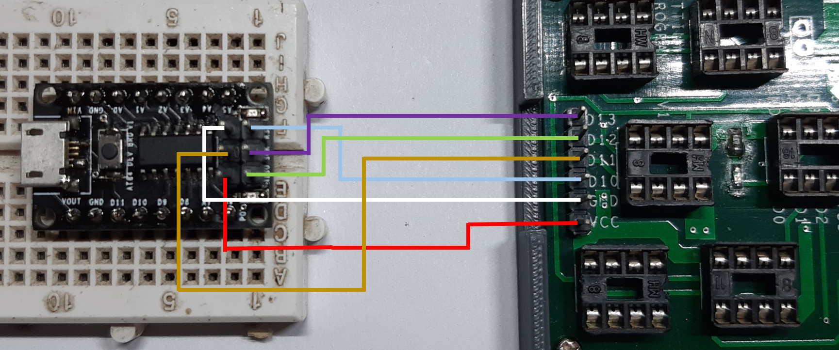
Now wire the SPI pins of “Arduino as ISP” Programmer with Attiny84
VCC of Attiny84 to VCC of Programmer
GND to GND
Reset of attiny – D10
MOSI of attiny – D11
MISO of attiny – D12
SCK of attiny – D13
After wiring, it’s time to flash the Microcontroller with sketch tweaked according to the pinout of attiny84. I used the Blink sketch in which I’ve added D8 as Output Pin in place of LED_BUILTIN.
blink sketch will toggle the D8 pin for testing the board.
Flashing the board-step1open tool menu, and select the attiny84 from boards.
do not change any setting.
select Arduino as ISP as programmer
and then burn the bootloader.
wait for few seconds and you will be greeted with a done burning bootloader message.
step4now goto sketch menu and hit "upload using programmer"
Result
And as we can see, Attiny84 is running a Blink sketch which is toggling an LED connected to D8 of the Microcontroller.
Blinking an LED is no fun, let’s try to drive a stepper motor with this attiny84 board by using an A4988 Stepper Motor Driver!
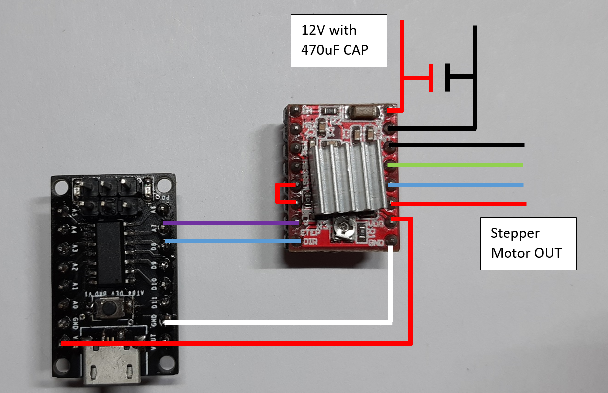
Wire attiny84 with A4988 Driver according to this arrangement-
STEP Pin- D7 of attiny
DIR Pin- D8 of attiny
VDD- VCC of attiny
GND to GND
Result
So now you know how to program an ATtiny84. But to really understand the chip, you have to read its datasheet. It’s complex and can seem incomprehensible in the beginning, but if you grasp the important things it will be quite handy and useful in many ways.
Using Attiny84 as a Microcontroller replacement is applicable in a scenario where your project is really minimal and it needs to be reliable, Cheap, and easy to reproduce.
Basically, you cannot use it as a “Development board alternative” but you can use it in later steps of developing a final version of any low spec project as the main microcontroller.
Also, it’s pretty fun to make your own Boards and run things with it.
Programming attiny84 with Arduino can be pretty tricky so if you run into some issue don’t give up, just check the wiring and redo the whole programming step.
Sometimes your jumper wires can be faulty and might affect the Flashing process. Also, do not forget to add 10uf CAP between Reset Pin and GND
Good luck to you in starting out with the Attiny84!


_ztBMuBhMHo.jpg?auto=compress%2Cformat&w=48&h=48&fit=fill&bg=ffffff)


Comments
Please log in or sign up to comment.