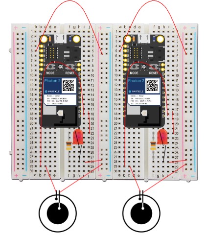
This project uses two piezoelectric sensors and two particle photon 2 to generate a signal that will light an LED bulb when it is touched. The project uses two separate proton boards so that the sensor and LED can be placed in different locations. This enables the touch sensor to be implemented in many different ways, such as embedding the sensor in a countertop and turning on an overhead light when its touched, or attaching the sensor to a doorbell to create a silent notification by turning on a light. In this project's case, the piezo sensor transmits the data through the particle photon and tells the LED bulb when to turn on. The first photon also sends that signal through the particle cloud to the second photon, telling it to turn on the second LED bulb. This allows for communication between the two photons from completely separate locations, enabling it to function well as a morse code communicator or just an indication that the piezo sensed pressure on it from one of the locations.
Piezo-electric SensorThe piezo sensor is a unique sensor indeed. The way it functions is through any type of pressure, or vibrations that act onto it. It only outputs a signal just like most sensors, but its simplicity does not discredit its overall function.
With every bit of pressure acted on the sensor, the signal output is produced through changes of voltage. These voltage changes can range depending on how much force is being put on the sensor, or in other cases, the frequency of vibrations it is undergoing.
Particle Photon PinsThe pin used for input is D1. This processes the data from the piezoelectric sensor, and sends this data to the output pin, D0. Both D0 and D1 pins are digital inputs and outputs. They can be used to send or receive signals, however, they must be specifically coded as either an input or output function.
int piezo = D0;
int LED = D1;

void setup() {
    pinMode(LED, OUTPUT);
    pinMode(piezo, INPUT);
}
The pictured code allows any pressure on the sensor to be directly shown by the illumination of the LED. The 3V3 pin allows for power to be supplied to the positive terminals so that the LED can be lit. LED is supplied a voltage, however, the light will only transmit if there is pressure on the piezoelectric sensor.
From the schematic above, you can see how both breadboards are wired exactly the same. Both have the same purpose; to send and receive the transmitted light over wi-fi. The 10 kohm resistor's purpose is to regulate the electrical flow through the LED so that the LED does not burn out.
LED TransmitterMuch like how a walkie-talkie operates, where with a touch of a button a message can be sent and received, this project simulates the same function of communication to send and receive signals through LEDs and piezo sensors. The project can be enhanced by using morse code to send complex messages from one location to another.
Both photon devices have the same coding and wiring, however, they are connected to each other through the particle cloud, so that they can receive the message being sent. The reason both lights turn on is so that the device sending the message can confirm it is being sent. This idea is similar to seeing a text message with a check mark to indicate that it has been sent or received.
GraphingFor the graphing, Ubidots was used. For this graph specifically, it traced the drops in voltages that the piezo sensor was transmitting to allow for the LED to light up.
We can see how the voltage was fluctuating since the voltage outputs determine whether the light turns on or not. It seems to start off at 1V and then spikes to 2.5V, then drops to 1.5V. These voltages seem very consistent determining the voltage values. Either the sensor itself is very accurate or the data is being generalized and averaged per a certain amount of time.
For Live data, click on the link below:
https://iot-data-service-us.s3.amazonaws.com/device-label_device_voltage_variable_WkjP.csv
Additional Images


Comments
Please log in or sign up to comment.