


Hardware components | ||||||
 |
| × | 1 | |||
 |
| × | 1 | |||
| × | 2 | ||||
| × | 2 | ||||
Software apps and online services | ||||||
 |
| |||||
Hand tools and fabrication machines | ||||||
 |
| |||||
 |
| |||||
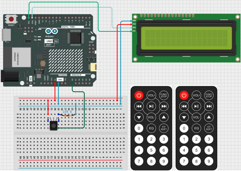
My project with a senior friend during the summer break of the tenth grade. The chosen project is called “Guess the number” which is a portable gaming device for 2 players that consists of an Arduino Uno R4 and 2 IR remotes with IR receivers using C/C++ languages.
Theory of OperationThe gaming device consists of 2 parts: the controller and the display. The controller uses IR technology so players can play the game from afar and the display includes the LCD screen and a Arduino Uno R4 board acting as the brain of the device.
There will be a randomly generated number that the players have to guess, the player will take turns guessing the number by pressing the number button on the controller. The first to guess the correct number will win.
The Prototype DesignThe firmware uses C++ and IRremote.hpp, LiquidCrystal_I2C.h library that is compatible with Arduino Uno R4. The software used for programming and flashing the code is Platform.io in VScode. Credit to Armin Joachimsmeyer for the IR Library. The building setting is as follows:
https://github.com/Arduino-IRremote/Arduino-IRremote
/*
 * SimpleReceiver.cpp
 *
 * Demonstrates receiving ONLY NEC protocol IR codes with IRremote
 * If no protocol is defined, all protocols (except Bang&Olufsen) are active.
 *
 *  This file is part of Arduino-IRremote https://github.com/Arduino-IRremote/Arduino-IRremote.
 *
 ************************************************************************************
 * MIT License. "Credit to Armin Joachimsmeyer for the IR Library"
 *
 * Copyright (c) 2020-2023 Armin Joachimsmeyer
 *
 * Permission is hereby granted, free of charge, to any person obtaining a copy
 * of this software and associated documentation files (the "Software"), to deal
 * in the Software without restriction, including without limitation the rights
 * to use, copy, modify, merge, publish, distribute, sublicense, and/or sell
 * copies of the Software, and to permit persons to whom the Software is furnished
 * to do so, subject to the following conditions:
 *
 * The above copyright notice and this permission notice shall be included in all
 * copies or substantial portions of the Software.
 *
 * THE SOFTWARE IS PROVIDED "AS IS", WITHOUT WARRANTY OF ANY KIND, EXPRESS OR IMPLIED,
 * INCLUDING BUT NOT LIMITED TO THE WARRANTIES OF MERCHANTABILITY, FITNESS FOR A
 * PARTICULAR PURPOSE AND NONINFRINGEMENT. IN NO EVENT SHALL THE AUTHORS OR COPYRIGHT
 * HOLDERS BE LIABLE FOR ANY CLAIM, DAMAGES OR OTHER LIABILITY, WHETHER IN AN ACTION OF
 * CONTRACT, TORT OR OTHERWISE, ARISING FROM, OUT OF OR IN CONNECTION WITH THE SOFTWARE
 * OR THE USE OR OTHER DEALINGS IN THE SOFTWARE.
 *
 ************************************************************************************
 */

#include <Arduino.h>

/*
 * Specify which protocol(s) should be used for decoding.
 * If no protocol is defined, all protocols (except Bang&Olufsen) are active.
 * This must be done before the #include <IRremote.hpp>
 */
// #define DECODE_DENON        // Includes Sharp
// #define DECODE_JVC
// #define DECODE_KASEIKYO
// #define DECODE_PANASONIC    // alias for DECODE_KASEIKYO
// #define DECODE_LG
#define DECODE_NEC // Includes Apple and Onkyo. To enable all protocols , just comment/disable this line.
// #define DECODE_SAMSUNG
// #define DECODE_SONY
// #define DECODE_RC5
// #define DECODE_RC6

// #define DECODE_BOSEWAVE
// #define DECODE_LEGO_PF
// #define DECODE_MAGIQUEST
// #define DECODE_WHYNTER
// #define DECODE_FAST

// #define DECODE_DISTANCE_WIDTH // Universal decoder for pulse distance width protocols
// #define DECODE_HASH         // special decoder for all protocols

// #define DECODE_BEO          // This protocol must always be enabled manually, i.e. it is NOT enabled if no protocol is defined. It prevents decoding of SONY!

// #define DEBUG               // Activate this for lots of lovely debug output from the decoders.

// #define RAW_BUFFER_LENGTH  750 // For air condition remotes it requires 750. Default is 200.

/*
 * This include defines the actual pin number for pins like IR_RECEIVE_PIN, IR_SEND_PIN for many different boards and architectures
 */
#include "PinDefinitionsAndMore.h"
#include <IRremote.hpp> // include the library
#include <LiquidCrystal_I2C.h>

LiquidCrystal_I2C lcd(0x27, 16, 2);

String data = "";
String number = String(random(1, 10000) % 100);
int small = 0;
int big = 100;
void ClearRow(int row);
void setup()
{
  Serial.begin(115200);
  while (!Serial)
    ; // Wait for Serial to become available. Is optimized away for some cores.

  // Just to know which program is running on my Arduino
  Serial.println(F("START " __FILE__ " from " __DATE__ "\r\nUsing library version " VERSION_IRREMOTE));

  // Start the receiver and if not 3. parameter specified, take LED_BUILTIN pin from the internal boards definition as default feedback LED
  IrReceiver.begin(IR_RECEIVE_PIN, ENABLE_LED_FEEDBACK);

  Serial.print(F("Ready to receive IR signals of protocols: "));
  printActiveIRProtocols(&Serial);
  Serial.println(F("at pin " STR(IR_RECEIVE_PIN)));
  lcd.init(); // initialize the lcd
  // Print a message to the LCD.
  lcd.backlight();
  lcd.print("Find X");
}

void loop()
{
  /*
   * Check if received data is available and if yes, try to decode it.
   * Decoded result is in the IrReceiver.decodedIRData structure.
   *
   * E.g. command is in IrReceiver.decodedIRData.command
   * address is in command is in IrReceiver.decodedIRData.address
   * and up to 32 bit raw data in IrReceiver.decodedIRData.decodedRawData
   */
  String InputNumber = "";
  if (IrReceiver.decode())
  {

    /*
     * Print a summary of received data
     */
    if (IrReceiver.decodedIRData.protocol == UNKNOWN)
    {
      Serial.println(F("Received noise or an unknown (or not yet enabled) protocol"));
      // We have an unknown protocol here, print extended info
      IrReceiver.printIRResultRawFormatted(&Serial, true);
      IrReceiver.resume(); // Do it here, to preserve raw data for printing with printIRResultRawFormatted()
    }
    else
    {
    }
    Serial.println();

    /*
     * Finally, check the received data and perform actions according to the received command
     */

    switch (IrReceiver.decodedIRData.command)
    {
    case 0x16:
      data += "0";
      break;
    case 0x18:
      data += "2";
      break;
    case 0xC:
      data += "1";
      break;
    case 0x5E:
      data += "3";
      break;
    case 0x8:
      data += "4";
      break;
    case 0x1C:
      data += "5";
      break;
    case 0x5A:
      data += "6";
      break;
    case 0x42:
      data += "7";
      break;
    case 0x52:
      data += "8";
      break;
    case 0x4A:
      data += "9";
      break;
    case 0xD:
      InputNumber = data;
      if (InputNumber.length() > number.length())
      {
        Serial.println("Please Input Again");
        lcd.setCursor(0, 0);
        lcd.print("Input Again");
      }
      else
      {
        int IntInputNumber = InputNumber.toInt();
        int Intnumber = number.toInt();
        if (IntInputNumber == Intnumber)
        {
          Serial.println("Congratulations you guessed the correct number");
          lcd.setCursor(0, 0);
          lcd.print("Congratulations");
        }
        else if (IntInputNumber > Intnumber)
        {
          String output = "";
          big = IntInputNumber;
          Serial.print("Bigger than: ");
          Serial.print(small);
          Serial.print(", ");
          Serial.print("Smaller than: ");
          Serial.println(big);
          output = String(small) + " < " + "X" + " < " + String(big);
          ClearRow(0);
          lcd.setCursor(0, 0);
          lcd.print(output);
        }
        else if (IntInputNumber < Intnumber)
        {
          String output = "";
          small = IntInputNumber;
          Serial.print("Bigger than: ");
          Serial.print(small);
          Serial.print(", ");
          Serial.print("Smaller than: ");
          Serial.println(big);
          output = String(small) + " < " + "X" + " < " + String(big);
          ClearRow(0);
          lcd.setCursor(0, 0);
          lcd.print(output);
        };
      }
      data = "";
      break;
    default:
      Serial.println("Invalid Input");
      break;
    }
    if (data != "")
    {
      Serial.print(data);
      ClearRow(1);
      lcd.setCursor(0, 1);
      lcd.print(data);
    }
    delay(20);
    IrReceiver.resume();
  }
}

void ClearRow(int row)
{
  lcd.setCursor(0, row);
  lcd.print("                     ");
}
/*
 *  PinDefinitionsAndMore.h
 *
 *  Contains pin definitions for IRremote examples for various platforms
 *  as well as definitions for feedback LED and tone() and includes
 *
 *  Copyright (C) 2021-2023  Armin Joachimsmeyer
 *  armin.joachimsmeyer@gmail.com "Credit to Armin Joachimsmeyer for the IR Library"
 *
 *  This file is part of IRremote https://github.com/Arduino-IRremote/Arduino-IRremote.
 *
 *  Arduino-IRremote is free software: you can redistribute it and/or modify
 *  it under the terms of the GNU General Public License as published by
 *  the Free Software Foundation, either version 3 of the License, or
 *  (at your option) any later version.
 *
 *  This program is distributed in the hope that it will be useful,
 *  but WITHOUT ANY WARRANTY; without even the implied warranty of
 *  MERCHANTABILITY or FITNESS FOR A PARTICULAR PURPOSE.
 *  See the GNU General Public License for more details.
 *
 *  You should have received a copy of the GNU General Public License
 *  along with this program. If not, see <http://www.gnu.org/licenses/gpl.html>.
 *
 */

/*
 * Pin mapping table for different platforms
 *
 * Platform     IR input    IR output   Tone      Core/Pin schema
 * --------------------------------------------------------------
 * DEFAULT/AVR  2           3           4         Arduino
 * ATtinyX5     0|PB0       4|PB4       3|PB3     ATTinyCore
 * ATtiny167    3|PA3       2|PA2       7|PA7     ATTinyCore
 * ATtiny167    9|PA3       8|PA2       5|PA7     Digispark original core
 * ATtiny84      |PB2        |PA4        |PA3     ATTinyCore
 * ATtiny88     3|PD3       4|PD4       9|PB1     ATTinyCore
 * ATtiny3217  18|PA1      19|PA2      20|PA3     MegaTinyCore
 * ATtiny1604   2           3|PA5       %
 * ATtiny816   14|PA1      16|PA3       1|PA5     MegaTinyCore
 * ATtiny1614   8|PA1      10|PA3       1|PA5     MegaTinyCore
 * SAMD21       3           4           5
 * ESP8266      14|D5       12|D6       %
 * ESP32        15          4          27
 * ESP32-C3     2           3           4
 * BluePill     PA6         PA7       PA3
 * APOLLO3      11          12          5
 * RP2040       3|GPIO15    4|GPIO16    5|GPIO17
 */
// #define _IR_MEASURE_TIMING // For debugging purposes.

#if defined(__AVR__)
#if defined(__AVR_ATtiny25__) || defined(__AVR_ATtiny45__) || defined(__AVR_ATtiny85__) // Digispark board. For use with ATTinyCore.
#include "ATtinySerialOut.hpp"                                                          // TX is at pin 2 - Available as Arduino library "ATtinySerialOut". Saves 700 bytes program memory and 70 bytes RAM for ATtinyCore.
#define IR_RECEIVE_PIN PIN_PB0
#define IR_SEND_PIN PIN_PB4 // Pin 2 is serial output with ATtinySerialOut. Pin 1 is internal LED and Pin3 is USB+ with pullup on Digispark board.
#define TONE_PIN PIN_PB3
#define _IR_TIMING_TEST_PIN PIN_PB3

#elif defined(__AVR_ATtiny87__) || defined(__AVR_ATtiny167__) // Digispark pro board
#include "ATtinySerialOut.hpp"                                // Available as Arduino library "ATtinySerialOut"
// For ATtiny167 Pins PB6 and PA3 are usable as interrupt source.
#if defined(ARDUINO_AVR_DIGISPARKPRO)
// For use with Digispark original core
#define IR_RECEIVE_PIN 9       // PA3 - on Digispark board labeled as pin 9
// #define IR_RECEIVE_PIN  14 // PB6 / INT0 is connected to USB+ on DigisparkPro boards
#define IR_SEND_PIN 8          // PA2 - on Digispark board labeled as pin 8
#define TONE_PIN 5             // PA7 - on Digispark board labeled as pin 5
#define _IR_TIMING_TEST_PIN 10 // PA4
#else
// For use with ATTinyCore
#define IR_RECEIVE_PIN PIN_PA3 // On Digispark board labeled as pin 9 - INT0 is connected to USB+ on DigisparkPro boards
#define IR_SEND_PIN PIN_PA2    // On Digispark board labeled as pin 8
#define TONE_PIN PIN_PA7       // On Digispark board labeled as pin 5
#endif

#elif defined(__AVR_ATtiny84__) // For use with ATTinyCore
#include "ATtinySerialOut.hpp"  // Available as Arduino library "ATtinySerialOut". Saves 128 bytes program memory.
#define IR_RECEIVE_PIN PIN_PB2  // INT0
#define IR_SEND_PIN PIN_PA4
#define TONE_PIN PIN_PA3
#define _IR_TIMING_TEST_PIN PIN_PA5

#elif defined(__AVR_ATtiny88__)     // MH-ET Tiny88 board. For use with ATTinyCore.
#include "ATtinySerialOut.hpp"      // Available as Arduino library "ATtinySerialOut". Saves 128 bytes program memory.
// Pin 6 is TX, pin 7 is RX
#define IR_RECEIVE_PIN PIN_PD3      // 3 - INT1
#define IR_SEND_PIN PIN_PD4         // 4
#define TONE_PIN PIN_PB1            // 9
#define _IR_TIMING_TEST_PIN PIN_PB0 // 8

#elif defined(__AVR_ATtiny1616__) || defined(__AVR_ATtiny3216__) || defined(__AVR_ATtiny3217__) // For use with megaTinyCore
// Tiny Core Dev board
// https://www.tindie.com/products/xkimi/tiny-core-16-dev-board-attiny1616/ - Out of Stock
// https://www.tindie.com/products/xkimi/tiny-core-32-dev-board-attiny3217/ - Out of Stock
#define IR_RECEIVE_PIN PIN_PA1                                                                  // use 18 instead of PIN_PA1 for TinyCore32
#define IR_SEND_PIN PIN_PA2                                                                     // 19
#define TONE_PIN PIN_PA3                                                                        // 20
#define APPLICATION_PIN PIN_PA0                                                                 // 0
#undef LED_BUILTIN                                                                              // No LED available on the TinyCore 32 board, take the one on the programming board which is connected to the DAC output
#define LED_BUILTIN PIN_PA6                                                                     // use 2 instead of PIN_PA6 for TinyCore32

#elif defined(__AVR_ATtiny816__) // For use with megaTinyCore
#define IR_RECEIVE_PIN PIN_PA1   // 14
#define IR_SEND_PIN PIN_PA1      // 16
#define TONE_PIN PIN_PA5         // 1
#define APPLICATION_PIN PIN_PA4  // 0
#undef LED_BUILTIN               // No LED available, take the one which is connected to the DAC output
#define LED_BUILTIN PIN_PB5      // 4

#elif defined(__AVR_ATtiny1614__) // For use with megaTinyCore
#define IR_RECEIVE_PIN PIN_PA1    // 8
#define IR_SEND_PIN PIN_PA3       // 10
#define TONE_PIN PIN_PA5          // 1
#define APPLICATION_PIN PIN_PA4   // 0

#elif defined(__AVR_ATtiny1604__) // For use with megaTinyCore
#define IR_RECEIVE_PIN PIN_PA6    // 2 - To be compatible with interrupt example, pin 2 is chosen here.
#define IR_SEND_PIN PIN_PA7       // 3
#define APPLICATION_PIN PIN_PB2   // 5

#define tone(...) void() // Define as void, since TCB0_INT_vect is also used by tone()
#define noTone(a) void()
#define TONE_PIN 42 // Dummy for examples using it

#elif defined(__AVR_ATmega1284__) || defined(__AVR_ATmega1284P__) || defined(__AVR_ATmega644__) || defined(__AVR_ATmega644P__) || defined(__AVR_ATmega324P__) || defined(__AVR_ATmega324A__) || defined(__AVR_ATmega324PA__) || defined(__AVR_ATmega164A__) || defined(__AVR_ATmega164P__) || defined(__AVR_ATmega32__) || defined(__AVR_ATmega16__) || defined(__AVR_ATmega8535__) || defined(__AVR_ATmega64__) || defined(__AVR_ATmega128__) || defined(__AVR_ATmega1281__) || defined(__AVR_ATmega2561__) || defined(__AVR_ATmega8515__) || defined(__AVR_ATmega162__)
#define IR_RECEIVE_PIN 2
#define IR_SEND_PIN 13
#define TONE_PIN 4
#define APPLICATION_PIN 5
#define ALTERNATIVE_IR_FEEDBACK_LED_PIN 6 // E.g. used for examples which use LED_BUILDIN for example output.
#define _IR_TIMING_TEST_PIN 7

#else                    // Default as for ATmega328 like on Uno, Nano, Leonardo, Teensy 2.0 etc.
#define IR_RECEIVE_PIN 2 // To be compatible with interrupt example, pin 2 is chosen here.
#define IR_SEND_PIN 3
#define TONE_PIN 4
#define APPLICATION_PIN 5
#define ALTERNATIVE_IR_FEEDBACK_LED_PIN 6 // E.g. used for examples which use LED_BUILDIN for example output.
#define _IR_TIMING_TEST_PIN 7

#if defined(ARDUINO_AVR_PROMICRO) // Sparkfun Pro Micro is __AVR_ATmega32U4__ but has different external circuit
// We have no built in LED at pin 13 -> reuse RX LED
#undef LED_BUILTIN
#define LED_BUILTIN LED_BUILTIN_RX
#endif
#endif // defined(__AVR_ATtiny25__)...

#elif defined(ARDUINO_ARCH_RENESAS_UNO) // Uno R4
// To be compatible with Uno R3.
#define IR_RECEIVE_PIN 2
#define IR_SEND_PIN 3
#define TONE_PIN 4
#define APPLICATION_PIN 5
#define ALTERNATIVE_IR_FEEDBACK_LED_PIN 6 // E.g. used for examples which use LED_BUILDIN for example output.
#define _IR_TIMING_TEST_PIN 7

#elif defined(ESP8266)
#define FEEDBACK_LED_IS_ACTIVE_LOW // The LED on my board (D4) is active LOW
#define IR_RECEIVE_PIN 14          // D5
#define IR_SEND_PIN 12             // D6 - D4/pin 2 is internal LED
#define _IR_TIMING_TEST_PIN 2      // D4
#define APPLICATION_PIN 13         // D7

#define tone(...) void() // tone() inhibits receive timer
#define noTone(a) void()
#define TONE_PIN 42 // Dummy for examples using it#

#elif defined(ARDUINO_NOLOGO_ESP32C3_SUPER_MINI)
#define FEEDBACK_LED_IS_ACTIVE_LOW // The LED on my board (D8) is active LOW
#define IR_RECEIVE_PIN 2
#define IR_SEND_PIN 3
#define TONE_PIN 4
#define APPLICATION_PIN 10

#elif defined(CONFIG_IDF_TARGET_ESP32C3) || defined(ARDUINO_ESP32C3_DEV)
#define NO_LED_FEEDBACK_CODE // The  WS2812 on pin 8 of AI-C3 board crashes if used as receive feedback LED, other I/O pins are working...
#define IR_RECEIVE_PIN 6
#define IR_SEND_PIN 7
#define TONE_PIN 10
#define APPLICATION_PIN 18

#elif defined(ESP32)
#include <Arduino.h>

// tone() is included in ESP32 core since 2.0.2
#if !defined(ESP_ARDUINO_VERSION_VAL)
#define ESP_ARDUINO_VERSION_VAL(major, minor, patch) 12345678
#endif
#if ESP_ARDUINO_VERSION <= ESP_ARDUINO_VERSION_VAL(2, 0, 2)
#define TONE_LEDC_CHANNEL 1 // Using channel 1 makes tone() independent of receiving timer -> No need to stop receiving timer.
void tone(uint8_t aPinNumber, unsigned int aFrequency)
{
  ledcAttachPin(aPinNumber, TONE_LEDC_CHANNEL);
  ledcWriteTone(TONE_LEDC_CHANNEL, aFrequency);
}
void tone(uint8_t aPinNumber, unsigned int aFrequency, unsigned long aDuration)
{
  ledcAttachPin(aPinNumber, TONE_LEDC_CHANNEL);
  ledcWriteTone(TONE_LEDC_CHANNEL, aFrequency);
  delay(aDuration);
  ledcWriteTone(TONE_LEDC_CHANNEL, 0);
}
void noTone(uint8_t aPinNumber)
{
  ledcWriteTone(TONE_LEDC_CHANNEL, 0);
}
#endif                      // ESP_ARDUINO_VERSION  <= ESP_ARDUINO_VERSION_VAL(2, 0, 2)

#define IR_RECEIVE_PIN 15  // D15
#define IR_SEND_PIN 4      // D4
#define TONE_PIN 27        // D27 25 & 26 are DAC0 and 1
#define APPLICATION_PIN 16 // RX2 pin

#elif defined(ARDUINO_ARCH_STM32) || defined(ARDUINO_ARCH_STM32F1) // BluePill
// Timer 3 blocks PA6, PA7, PB0, PB1 for use by Servo or tone()
#define IR_RECEIVE_PIN PA6
#define IR_RECEIVE_PIN_STRING "PA6"
#define IR_SEND_PIN PA7
#define IR_SEND_PIN_STRING "PA7"
#define TONE_PIN PA3
#define _IR_TIMING_TEST_PIN PA5
#define APPLICATION_PIN PA2
#define APPLICATION_PIN_STRING "PA2"
#if defined(ARDUINO_GENERIC_STM32F103C) || defined(ARDUINO_BLUEPILL_F103C8)
// BluePill LED is active low
#define FEEDBACK_LED_IS_ACTIVE_LOW
#endif

#elif defined(ARDUINO_ARCH_APOLLO3) // Sparkfun Apollo boards
#define IR_RECEIVE_PIN 11
#define IR_SEND_PIN 12
#define TONE_PIN 5

#elif defined(ARDUINO_ARCH_MBED) && defined(ARDUINO_ARCH_MBED_NANO) // Arduino Nano 33 BLE and Arduino Nano Connect layout for MBED
// Must be before ARDUINO_ARCH_RP2040, since it is the layout for the MBED core of Arduino Nano Connect
#define IR_RECEIVE_PIN 3                                            // GPIO15 Start with pin 3 since pin 2|GPIO25 is connected to LED on Pi pico
#define IR_SEND_PIN 4                                               // GPIO16
#define TONE_PIN 5
#define APPLICATION_PIN 6
#define ALTERNATIVE_IR_FEEDBACK_LED_PIN 7 // E.g. used for examples which use LED_BUILDIN for example output.
#define _IR_TIMING_TEST_PIN 8

#elif defined(ARDUINO_ARCH_RP2040) // Arduino Nano Connect, Pi Pico with arduino-pico core https://github.com/earlephilhower/arduino-pico
#define IR_RECEIVE_PIN 15          // GPIO15 to be compatible with the Arduino Nano RP2040 Connect (pin3)
#define IR_SEND_PIN 16             // GPIO16
#define TONE_PIN 17
#define APPLICATION_PIN 18
#define ALTERNATIVE_IR_FEEDBACK_LED_PIN 19 // E.g. used for examples which use LED_BUILDIN for example output.
#define _IR_TIMING_TEST_PIN 20

// If you program the Nano RP2040 Connect with this core, then you must redefine LED_BUILTIN
// and use the external reset with 1 kOhm to ground to enter UF2 mode
#undef LED_BUILTIN
#define LED_BUILTIN 6

#elif defined(PARTICLE) // !!!UNTESTED!!!
#define IR_RECEIVE_PIN A4
#define IR_SEND_PIN A5 // Particle supports multiple pins

#define LED_BUILTIN D7

/*
 * 4 times the same (default) layout for easy adaption in the future
 */
#elif defined(TEENSYDUINO) // Teensy 2.0 is handled at default for ATmega328 like on Uno, Nano, Leonardo etc.
#define IR_RECEIVE_PIN 2
#define IR_SEND_PIN 3
#define TONE_PIN 4
#define APPLICATION_PIN 5
#define ALTERNATIVE_IR_FEEDBACK_LED_PIN 6 // E.g. used for examples which use LED_BUILDIN for example output.
#define _IR_TIMING_TEST_PIN 7

#elif defined(ARDUINO_ARCH_MBED) // Arduino Nano 33 BLE
#define IR_RECEIVE_PIN 2
#define IR_SEND_PIN 3
#define TONE_PIN 4
#define APPLICATION_PIN 5
#define ALTERNATIVE_IR_FEEDBACK_LED_PIN 6 // E.g. used for examples which use LED_BUILDIN for example output.
#define _IR_TIMING_TEST_PIN 7

#elif defined(ARDUINO_ARCH_SAMD) || defined(ARDUINO_ARCH_SAM)
#define IR_RECEIVE_PIN 2
#define IR_SEND_PIN 3
#define TONE_PIN 4
#define APPLICATION_PIN 5
#define ALTERNATIVE_IR_FEEDBACK_LED_PIN 6 // E.g. used for examples which use LED_BUILDIN for example output.
#define _IR_TIMING_TEST_PIN 7

#if !defined(ARDUINO_SAMD_ADAFRUIT) && !defined(ARDUINO_SEEED_XIAO_M0)
// On the Zero and others we switch explicitly to SerialUSB
#define Serial SerialUSB
#endif

// Definitions for the Chinese SAMD21 M0-Mini clone, which has no led connected to D13/PA17.
// Attention!!! D2 and D4 are swapped on these boards!!!
// If you connect the LED, it is on pin 24/PB11. In this case activate the next two lines.
// #undef LED_BUILTIN
// #define LED_BUILTIN 24 // PB11
// As an alternative you can choose pin 25, it is the RX-LED pin (PB03), but active low.In this case activate the next 3 lines.
// #undef LED_BUILTIN
// #define LED_BUILTIN 25 // PB03
// #define FEEDBACK_LED_IS_ACTIVE_LOW // The RX LED on the M0-Mini is active LOW

#elif defined(NRF51) // BBC micro:bit
#define IR_RECEIVE_PIN 2
#define IR_SEND_PIN 3
#define APPLICATION_PIN 1
#define _IR_TIMING_TEST_PIN 4

#define tone(...) void() // no tone() available
#define noTone(a) void()
#define TONE_PIN 42 // Dummy for examples using it

#else
#warning Board / CPU is not detected using pre-processor symbols -> using default values, which may not fit. Please extend PinDefinitionsAndMore.h.
// Default valued for unidentified boards
#define IR_RECEIVE_PIN 2
#define IR_SEND_PIN 3
#define TONE_PIN 4
#define APPLICATION_PIN 5
#define ALTERNATIVE_IR_FEEDBACK_LED_PIN 6 // E.g. used for examples which use LED_BUILDIN for example output.
#define _IR_TIMING_TEST_PIN 7
#endif // defined(ESP8266)

#if defined(ESP32) || defined(ARDUINO_ARCH_RP2040) || defined(PARTICLE) || defined(ARDUINO_ARCH_MBED)
#define SEND_PWM_BY_TIMER // We do not have pin restrictions for this CPU's, so lets use the hardware PWM for send carrier signal generation
#else
#if defined(SEND_PWM_BY_TIMER)
#undef IR_SEND_PIN // SendPin is determined by timer! This avoids warnings in IRremote.hpp and IRTimer.hpp
#endif
#endif

#if !defined(FLASHEND)
#define FLASHEND 0xFFFF // Dummy value for platforms where FLASHEND is not defined
#endif

/*
 * Helper macro for getting a macro definition as string
 */
#if !defined(STR_HELPER)
#define STR_HELPER(x) #x
#define STR(x) STR_HELPER(x)
#endif


Comments
Please log in or sign up to comment.