


Hardware components | ||||||
 |
| × | 1 | |||
 |
| × | 1 | |||
Software apps and online services | ||||||
 |
| |||||
 |
| |||||
| ||||||
| ||||||
Hand tools and fabrication machines | ||||||
 |
| |||||
Imagine waking up in the morning and simply saying "Lights On, " and your room lights turn on instantly. As you start your day, you instruct "Fan On" while you sip your coffee, feeling the cool breeze. Later, as you wind down, you say "Mood Lights On" to create a relaxing ambiance with soft lighting. With offline keyword spotting, all this happens seamlessly without internet delays, ensuring a fast, private, and reliable experience.With the advancement of Edge AI and TinyML, smart home automation has become more efficient and accessible. This project demonstrates how to build a voice-controlled smart home automation system that operates entirely offline using TinyML. By leveraging the XIAO ESP32S3 Sense microcontroller, we enable local processing of voice commands like "Lights On" and "Lights Off" without relying on cloud services. This approach ensures privacy, reduces latency, and minimizes power consumption.
Key Features:
- Offline voice command recognition using TinyML.
- Control AC appliances via relays.
- Manual override switches for reliability.
- Energy-efficient design with sleep modes.
Components:
1. XIAO ESP32S3 Sense: Dual-core microcontroller with built-in microphone.
2. 1-Channel Relay Module: For switching AC appliances.
3. Buck Converter: Steps down voltage for microcontroller (5V output).
4. SPDT Switches: Manual control override.
5. *AC Light Bulb & Holder*: Demonstration load.
6. *Jumper Wires & PCB*: For circuit assembly.
Tools*:
- Soldering iron, multimeter, screwdrivers.
3. System Workflow- The XIAO ESP32S3 Sense continuously listens for voice commands using its onboard microphone.
- The TinyML model processes the audio input and detects specific keywords.
- Upon detecting a valid command, the microcontroller triggers the relay module to switch the respective device on or off.
- Manual control switches allow an alternative method of operating the devices.
Components:
Step 1.a: Circuit Design
The relay module circuit includes:
Relay Control:
XIAO’s D0 pin drives the relay coil via a transistor (not listed, but assumed in the circuit).
- XIAO’s D0 pin drives the relay coil via a transistor (not listed, but assumed in the circuit).
1N4007 diode across the relay coil for back-EMF protection.
- 1N4007 diode across the relay coil for back-EMF protection.
- Relay Control:
XIAO’s D0 pin drives the relay coil via a transistor (not listed, but assumed in the circuit).
1N4007 diode across the relay coil for back-EMF protection.
Status Indicators:
Red LED (330Ω resistor) shows power status.
- Red LED (330Ω resistor) shows power status.
Green LED (1kΩ resistor) indicates relay activation.
- Green LED (1kΩ resistor) indicates relay activation.
- Status Indicators:
Red LED (330Ω resistor) shows power status.
Green LED (1kΩ resistor) indicates relay activation.
Step 1.b: PCB Layout
Component Placement:
Position the XIAO’s footprint near the edge for easy access.
- Position the XIAO’s footprint near the edge for easy access.
Place the relay and LEDs close to their respective resistors.
- Place the relay and LEDs close to their respective resistors.
- Component Placement:
Position the XIAO’s footprint near the edge for easy access.
Place the relay and LEDs close to their respective resistors.
Trace Routing:
Use 20–30 mil traces for power lines.
- Use 20–30 mil traces for power lines.
Keep signal traces (D0 to relay) short to reduce noise.
- Keep signal traces (D0 to relay) short to reduce noise.
- Trace Routing:
Use 20–30 mil traces for power lines.
Keep signal traces (D0 to relay) short to reduce noise.
XIAO Integration:
Design headers/pads for the XIAO’s D0, 5V, and GND pins.
- Design headers/pads for the XIAO’s D0, 5V, and GND pins.
- XIAO Integration:
Design headers/pads for the XIAO’s D0, 5V, and GND pins.
Step 1.c: Generate Gerber Files
In Altium: File → Fabrication Outputs → Gerber Files.
- In Altium:
File → Fabrication Outputs → Gerber Files.
Include layers: Top Copper, Silkscreen, Drill.
- Include layers: Top Copper, Silkscreen, Drill.
Step 1.d. PCB Fabrication
Step 1: Prepare Copper Clad Sheet
Clean the Surface:
Scrub the copper sheet with steel wool to remove oxidation.
- Scrub the copper sheet with steel wool to remove oxidation.
Wipe with isopropyl alcohol for a grease-free surface.
- Wipe with isopropyl alcohol for a grease-free surface.
- Clean the Surface:
Scrub the copper sheet with steel wool to remove oxidation.
Wipe with isopropyl alcohol for a grease-free surface.
Step 2: Transfer Design
Heat Transfer Method:
Print the PCB layout on glossy paper (mirror image).
- Print the PCB layout on glossy paper (mirror image).
Place the paper on the copper sheet and run through a heat roller (180°C) for 5–10 minutes.
- Place the paper on the copper sheet and run through a heat roller (180°C) for 5–10 minutes.
Soak in water to remove the paper, leaving the toner on the copper.
- Soak in water to remove the paper, leaving the toner on the copper.
- Heat Transfer Method:
Print the PCB layout on glossy paper (mirror image).
Place the paper on the copper sheet and run through a heat roller (180°C) for 5–10 minutes.
Soak in water to remove the paper, leaving the toner on the copper.
Step 3: Etching
Etch in Ferric Chloride:
Submerge the copper sheet in ferric chloride solution (1:3 ratio with water).
- Submerge the copper sheet in ferric chloride solution (1:3 ratio with water).
Agitate gently until unwanted copper dissolves (10–30 minutes).
- Agitate gently until unwanted copper dissolves (10–30 minutes).
- Etch in Ferric Chloride:
Submerge the copper sheet in ferric chloride solution (1:3 ratio with water).
Agitate gently until unwanted copper dissolves (10–30 minutes).
Safety: Wear gloves and goggles.
- Safety: Wear gloves and goggles.
Clean the PCB:
Scrub off toner with steel wool.
- Scrub off toner with steel wool.
Rinse with water and dry.
- Rinse with water and dry.
- Clean the PCB:
Scrub off toner with steel wool.
Rinse with water and dry.
Drill Holes:
Use a 0.8–1mm drill bit for component leads.
- Use a 0.8–1mm drill bit for component leads.
- Drill Holes:
Use a 0.8–1mm drill bit for component leads.
Step 1.e Assembly & Testing
Step 1: Solder Components
Order of Assembly:
Resistors → LEDs → Diode → Relay → XIAO headers.
- Resistors → LEDs → Diode → Relay → XIAO headers.
- Order of Assembly:
Resistors → LEDs → Diode → Relay → XIAO headers.
Soldering Tips:
Heat the pad, not the component.
- Heat the pad, not the component.
Trim excess leads with wire cutters.
- Trim excess leads with wire cutters.
- Soldering Tips:
Heat the pad, not the component.
Trim excess leads with wire cutters.
Step 2: Continuity Check
Use a multimeter in continuity mode to verify:
No short circuits between 5V and GND.
- No short circuits between 5V and GND.
D0 pin connects to the relay control circuit.
- D0 pin connects to the relay control circuit.
- Use a multimeter in continuity mode to verify:
No short circuits between 5V and GND.
D0 pin connects to the relay control circuit.
Step 3: Functional Test
Power Up:
Connect 5V to the XIAO. The red LED should glow.
- Connect 5V to the XIAO. The red LED should glow.
- Power Up:
Connect 5V to the XIAO. The red LED should glow.
Relay Test:
Upload code to XIAO to toggle D0 (see code snippet below).
- Upload code to XIAO to toggle D0 (see code snippet below).
The green LED should light when the relay activates.
- The green LED should light when the relay activates.
- Relay Test:
Upload code to XIAO to toggle D0 (see code snippet below).
The green LED should light when the relay activates.
XIAO ESP32S3 Sense Introduction
A compact yet powerful development board designed to kickstart your journey into intelligent voice and vision AI. With its integrated camera sensor, digital microphone, and SD card support, this tiny board packs a punch, offering embedded ML computing power and photography capabilities. Whether you're delving into edge computing or exploring AI applications, the XIAO ESP32S3 Sense is your go-to tool for realizing innovative projects with ease and efficiency.
Edge Impulse Introduction
Edge Impulse is a platform for developing machine learning models specifically designed for edge devices and embedded systems. It provides a comprehensive set of tools and services that enable developers to quickly create, train, and deploy machine learning models without requiring deep expertise in machine learning.
Recording Audio with XIAO ESP32S3 Sense
Let's use the onboard SD Card reader to save.wav audio files, we need to habilitate the XIAO PSRAM first.
Insert the microSD card into the microSD card slot. Please note the direction of insertion, the side with the gold finger should face inward.
Then compile and upload the following program to XIAO ESP32S3.
/*
* WAV Recorder for Seeed XIAO ESP32S3 Sense
*
* NOTE: To execute this code, we will need to use the PSRAM
* function of the ESP-32 chip, so please turn it on before uploading.
* Tools>PSRAM: "OPI PSRAM"
*
* Adapted by M.Rovai @May23 from original Seeed code
*/
#include <I2S.h>
#include "FS.h"
#include "SD.h"
#include "SPI.h"
// make changes as needed
#define RECORD_TIME   10  // seconds, The maximum value is 240
#define WAV_FILE_NAME "data"
// do not change for best
#define SAMPLE_RATE 16000U
#define SAMPLE_BITS 16
#define WAV_HEADER_SIZE 44
#define VOLUME_GAIN 2
int fileNumber = 1;
String baseFileName;
bool isRecording = false;
void setup() {
Serial.begin(115200);
while (!Serial) ;
I2S.setAllPins(-1, 42, 41, -1, -1);
if (!I2S.begin(PDM_MONO_MODE, SAMPLE_RATE, SAMPLE_BITS)) {
Serial.println("Failed to initialize I2S!");
while (1) ;
}
if(!SD.begin(21)){
Serial.println("Failed to mount SD Card!");
while (1) ;
}
Serial.printf("Enter with the label name\n");
//record_wav();
}
void loop() {
if (Serial.available() > 0) {
String command = Serial.readStringUntil('\n');
command.trim();
if (command == "rec") {
isRecording = true;
} else {
baseFileName = command;
fileNumber = 1; // reset file number each time a new base file name is set
Serial.printf("Send rec for starting recording label \n");
}
}
if (isRecording && baseFileName != "") {
String fileName = "/" + baseFileName + "." + String(fileNumber) + ".wav";
fileNumber++;
record_wav(fileName);
delay(1000); // delay to avoid recording multiple files at once
isRecording = false;
}
}
void record_wav(String fileName)
{
uint32_t sample_size = 0;
uint32_t record_size = (SAMPLE_RATE * SAMPLE_BITS / 8) * RECORD_TIME;
uint8_t *rec_buffer = NULL;
Serial.printf("Start recording ...\n");
File file = SD.open(fileName.c_str(), FILE_WRITE);
// Write the header to the WAV file
uint8_t wav_header[WAV_HEADER_SIZE];
generate_wav_header(wav_header, record_size, SAMPLE_RATE);
file.write(wav_header, WAV_HEADER_SIZE);
// PSRAM malloc for recording
rec_buffer = (uint8_t *)ps_malloc(record_size);
if (rec_buffer == NULL) {
Serial.printf("malloc failed!\n");
while(1) ;
}
Serial.printf("Buffer: %d bytes\n", ESP.getPsramSize() - ESP.getFreePsram());
// Start recording
esp_i2s::i2s_read(esp_i2s::I2S_NUM_0, rec_buffer, record_size, &sample_size, portMAX_DELAY);
if (sample_size == 0) {
Serial.printf("Record Failed!\n");
} else {
Serial.printf("Record %d bytes\n", sample_size);
}
// Increase volume
for (uint32_t i = 0; i < sample_size; i += SAMPLE_BITS/8) {
(*(uint16_t *)(rec_buffer+i)) <<= VOLUME_GAIN;
}
// Write data to the WAV file
Serial.printf("Writing to the file ...\n");
if (file.write(rec_buffer, record_size) != record_size)
Serial.printf("Write file Failed!\n");
free(rec_buffer);
file.close();
Serial.printf("Recording complete: \n");
Serial.printf("Send rec for a new sample or enter a new label\n\n");
}
void generate_wav_header(uint8_t *wav_header, uint32_t wav_size, uint32_t sample_rate)
{
// See this for reference: http://soundfile.sapp.org/doc/WaveFormat/
uint32_t file_size = wav_size + WAV_HEADER_SIZE - 8;
uint32_t byte_rate = SAMPLE_RATE * SAMPLE_BITS / 8;
const uint8_t set_wav_header[] = {
'R', 'I', 'F', 'F', // ChunkID
file_size, file_size >> 8, file_size >> 16, file_size >> 24, // ChunkSize
'W', 'A', 'V', 'E', // Format
'f', 'm', 't', ' ', // Subchunk1ID
0x10, 0x00, 0x00, 0x00, // Subchunk1Size (16 for PCM)
0x01, 0x00, // AudioFormat (1 for PCM)
0x01, 0x00, // NumChannels (1 channel)
sample_rate, sample_rate >> 8, sample_rate >> 16, sample_rate >> 24, // SampleRate
byte_rate, byte_rate >> 8, byte_rate >> 16, byte_rate >> 24, // ByteRate
0x02, 0x00, // BlockAlign
0x10, 0x00, // BitsPerSample (16 bits)
'd', 'a', 't', 'a', // Subchunk2ID
wav_size, wav_size >> 8, wav_size >> 16, wav_size >> 24, // Subchunk2Size
};
memcpy(wav_header, set_wav_header, sizeof(set_wav_header));
}
Now, Compile and run the code and get samples of different elephant sounds. You can also capture noise and other sounds. The Serial monitor will prompt you to receive the label to be recorded.
Send the label (for example, l_on, l_off). The program will wait for another command: rec. And the program will start recording new samples every time a command rec is sent. The files will be saved as l_on.1.wav, l_on.2.wav, l_on.3.wav, etc. until a new label (for example, Noice) is sent. In this case, you should send the command rec for each new sample, which will be saved as Noice1.wav, Noice.2.wav, Noice.3.wav, etc. Ultimately, we will get the saved files on the SD card.
send the first label name first, through the serial monitor
Then send command rec and start recording the command using XIAO.
Collect both samples in same amount.
Use a card reader to save all the sound samples stored inside the SD card to your computer.
Training Exported Models with Edge Impulse
We should initiate a new project at Edge Impulse and give it the same name “mini”.
Once the project is created, select the Upload Data tool in the Data Acquisition section. Choose the files to be uploaded.
make sure to balance between train and test set.80/20 is the best recommended ratio.
All data on dataset have a 1s length, but the samples recorded in the previous section have 10s and must be split into 1s samples to be compatible. Click on three dots after the sample name and select Split sample.
Once inside the tool, split the data into 1-second records. If necessary, add or remove segments. This procedure should be repeated for all samples.
Goto Impulse design
An impulse takes raw data, uses signal processing to extract features, and then uses a learning block to classify new data. First, we will take the data points with a 1-second window, augmenting the data, sliding that window each 500ms. Note that the option zero-pad data is set. This is important to fill with zeros samples smaller than 1 second (in some cases, I reduced the 1000 ms window on the split tool to avoid noises and spikes).
The next step is to create the images to be trained in the next phase. We can keep the default parameter values or take advantage of the DSP Autotuneparameters option, which we will do.
We will use a Convolution Neural Network (CNN) model. The basic architecture is defined with two blocks of Conv1D + MaxPooling (with 8 and 16 neurons, respectively) and a 0.25 Dropout. And on the last layer, after Flattening four neurons, one for each class.
Performance calibrationNavigate to the 'Performance calibration' tab in Edge Impulse Studio.
Configure Test Settings:
Select Noise Labels: Identify labels representing background noise or silence.
Ignore Specific Labels: Choose any labels that should be disregarded during testing.
Choose Audio Sample Type: Opt for 'Simulated real world audio' to generate synthetic audio streams from your test dataset, or upload your own recordings in a.zip file.
- Run the Test: Click 'Run test' to initiate performance calibration. The system will evaluate your model's accuracy, focusing on false positives and false negatives.
Select and Save Configuration
- Review the suggested configurations presented on the False Acceptance Rate (FAR) and False Rejection Rate (FRR) chart.Edge Impulse Docs
- Choose a configuration that balances the trade-off between false positives and false negatives, aligning with your project's requirements.Edge Impulse Docs
- Click 'Save selected config' to apply this configuration during deployment.
Export as Arduino Library
Edge Impulse will package all the needed libraries, preprocessing functions, and trained models, downloading them to your computer. You should select the option Arduino Library and at the bottom, select Quantized (Int8) and press the button Build. When the Build button is selected, a Zip file will be created and downloaded to your computer.Deploying models to XIAO ESP32S3 Sense
Deploying models to XIAO ESP32S3 Sense
Upload the zip file to you Arduino IDE
Before we use the downloaded library, we need to enable the ESP NN Accelerator. For that, you can download a preliminary version from the project GitHub, unzip it, and replace the ESP NN folder with it under: src/edge-impulse-sdk/porting/espressif/ESP-NN, in your Arduino library folder.
Link Address: https://github.com/Mjrovai/XIAO-ESP32S3-Sense/blob/main/ESP-NN.zip
/* Edge Impulse Arduino examples
* Copyright (c) 2022 EdgeImpulse Inc.
*
* Permission is hereby granted, free of charge, to any person obtaining a copy
* of this software and associated documentation files (the "Software"), to deal
* in the Software without restriction, including without limitation the rights
* to use, copy, modify, merge, publish, distribute, sublicense, and/or sell
* copies of the Software, and to permit persons to whom the Software is
* furnished to do so, subject to the following conditions:
*
* The above copyright notice and this permission notice shall be included in
* all copies or substantial portions of the Software.
*
* THE SOFTWARE IS PROVIDED "AS IS", WITHOUT WARRANTY OF ANY KIND, EXPRESS OR
* IMPLIED, INCLUDING BUT NOT LIMITED TO THE WARRANTIES OF MERCHANTABILITY,
* FITNESS FOR A PARTICULAR PURPOSE AND NONINFRINGEMENT. IN NO EVENT SHALL THE
* AUTHORS OR COPYRIGHT HOLDERS BE LIABLE FOR ANY CLAIM, DAMAGES OR OTHER
* LIABILITY, WHETHER IN AN ACTION OF CONTRACT, TORT OR OTHERWISE, ARISING FROM,
* OUT OF OR IN CONNECTION WITH THE SOFTWARE OR THE USE OR OTHER DEALINGS IN THE
* SOFTWARE.
*/
// If your target is limited in memory remove this macro to save 10K RAM
#define EIDSP_QUANTIZE_FILTERBANK 0
/*
** NOTE: If you run into TFLite arena allocation issue.
**
** This may be due to may dynamic memory fragmentation.
** Try defining "-DEI_CLASSIFIER_ALLOCATION_STATIC" in boards.local.txt (create
** if it doesn't exist) and copy this file to
** <ARDUINO_CORE_INSTALL_PATH>/arduino/hardware/<mbed_core>/<core_version>/.
**
** See
** (https://support.arduino.cc/hc/en-us/articles/360012076960-Where-are-the-installed-cores-located-)
** to find where Arduino installs cores on your machine.
**
** If the problem persists then there's not enough memory for this model and application.
*/
/* Includes ---------------------------------------------------------------- */
#include <mini_inferencing.h>
#include <I2S.h>
#define SAMPLE_RATE 16000U
#define SAMPLE_BITS 16
#define RELAY_PIN D0 // Relay connected to D0
#define LED_BUILT_IN 21
/** Audio buffers, pointers and selectors */
typedef struct {
int16_t *buffer;
uint8_t buf_ready;
uint32_t buf_count;
uint32_t n_samples;
} inference_t;
static inference_t inference;
static const uint32_t sample_buffer_size = 2048;
static signed short sampleBuffer[sample_buffer_size];
static bool debug_nn = false; // Set this to true to see e.g. features generated from the raw signal
static bool record_status = true;
/**
* @brief Arduino setup function
*/
void setup()
{
// put your setup code here, to run once:
Serial.begin(115200);
// comment out the below line to cancel the wait for USB connection (needed for native USB)
while (!Serial);
Serial.println("Edge Impulse Inferencing Demo");
pinMode(RELAY_PIN, OUTPUT);
digitalWrite(RELAY_PIN, LOW); // Ensure relay is OFF initially
pinMode(LED_BUILT_IN, OUTPUT); // Set the pin as output
digitalWrite(LED_BUILT_IN, HIGH); //Turn off
I2S.setAllPins(-1, 42, 41, -1, -1);
if (!I2S.begin(PDM_MONO_MODE, SAMPLE_RATE, SAMPLE_BITS)) {
Serial.println("Failed to initialize I2S!");
while (1) ;
}
// summary of inferencing settings (from model_metadata.h)
ei_printf("Inferencing settings:\n");
ei_printf("\tInterval: ");
ei_printf_float((float)EI_CLASSIFIER_INTERVAL_MS);
ei_printf(" ms.\n");
ei_printf("\tFrame size: %d\n", EI_CLASSIFIER_DSP_INPUT_FRAME_SIZE);
ei_printf("\tSample length: %d ms.\n", EI_CLASSIFIER_RAW_SAMPLE_COUNT / 16);
ei_printf("\tNo. of classes: %d\n", sizeof(ei_classifier_inferencing_categories) / sizeof(ei_classifier_inferencing_categories[0]));
ei_printf("\nStarting continious inference in 2 seconds...\n");
ei_sleep(2000);
if (microphone_inference_start(EI_CLASSIFIER_RAW_SAMPLE_COUNT) == false) {
ei_printf("ERR: Could not allocate audio buffer (size %d), this could be due to the window length of your model\r\n", EI_CLASSIFIER_RAW_SAMPLE_COUNT);
return;
}
ei_printf("Recording...\n");
}
/**
* @brief Arduino main function. Runs the inferencing loop.
*/
void loop()
{
bool m = microphone_inference_record();
if (!m) {
ei_printf("ERR: Failed to record audio...\n");
return;
}
signal_t signal;
signal.total_length = EI_CLASSIFIER_RAW_SAMPLE_COUNT;
signal.get_data = µphone_audio_signal_get_data;
ei_impulse_result_t result = { 0 };
EI_IMPULSE_ERROR r = run_classifier(&signal, &result, debug_nn);
if (r != EI_IMPULSE_OK) {
ei_printf("ERR: Failed to run classifier (%d)\n", r);
return;
}
int pred_index = 0; // Initialize pred_index
float pred_value = 0; // Initialize pred_value
// print the predictions
ei_printf("Predictions ");
ei_printf("(DSP: %d ms., Classification: %d ms., Anomaly: %d ms.)",
result.timing.dsp, result.timing.classification, result.timing.anomaly);
ei_printf(": \n");
for (size_t ix = 0; ix < EI_CLASSIFIER_LABEL_COUNT; ix++) {
ei_printf(" %s: ", result.classification[ix].label);
ei_printf_float(result.classification[ix].value);
ei_printf("\n");
if (result.classification[ix].value > pred_value){
pred_index = ix;
pred_value = result.classification[ix].value;
}
}
for (size_t ix = 0; ix < EI_CLASSIFIER_LABEL_COUNT; ix++) {
if (strcmp(result.classification[ix].label, "l_on") == 0 && result.classification[ix].value >= 0.7) {
Serial.println("Lights are turned ON");
digitalWrite(RELAY_PIN, HIGH); // Turn relay ON
}
if (strcmp(result.classification[ix].label, "l_off") == 0 && result.classification[ix].value >= 0.7) {
Serial.println("Lights are turned OFF");
digitalWrite(RELAY_PIN, LOW); // Turn relay OFF
}
}
// Display inference result
if (pred_index >= .8){
digitalWrite(LED_BUILT_IN, LOW); //Turn on
}
else{
digitalWrite(LED_BUILT_IN, HIGH); //Turn off
}
#if EI_CLASSIFIER_HAS_ANOMALY == 1
ei_printf(" anomaly score: ");
ei_printf_float(result.anomaly);
ei_printf("\n");
#endif
}
static void audio_inference_callback(uint32_t n_bytes)
{
for(int i = 0; i < n_bytes>>1; i++) {
inference.buffer[inference.buf_count++] = sampleBuffer[i];
if(inference.buf_count >= inference.n_samples) {
inference.buf_count = 0;
inference.buf_ready = 1;
}
}
}
static void capture_samples(void* arg) {
const int32_t i2s_bytes_to_read = (uint32_t)arg;
size_t bytes_read = i2s_bytes_to_read;
while (record_status) {
/* read data at once from i2s - Modified for XIAO ESP2S3 Sense and I2S.h library */
// i2s_read((i2s_port_t)1, (void*)sampleBuffer, i2s_bytes_to_read, &bytes_read, 100);
esp_i2s::i2s_read(esp_i2s::I2S_NUM_0, (void*)sampleBuffer, i2s_bytes_to_read, &bytes_read, 100);
if (bytes_read <= 0) {
ei_printf("Error in I2S read : %d", bytes_read);
}
else {
if (bytes_read < i2s_bytes_to_read) {
ei_printf("Partial I2S read");
}
// scale the data (otherwise the sound is too quiet)
for (int x = 0; x < i2s_bytes_to_read/2; x++) {
sampleBuffer[x] = (int16_t)(sampleBuffer[x]) * 8;
}
if (record_status) {
audio_inference_callback(i2s_bytes_to_read);
}
else {
break;
}
}
}
vTaskDelete(NULL);
}
/**
* @brief Init inferencing struct and setup/start PDM
*
* @param[in] n_samples The n samples
*
* @return { description_of_the_return_value }
*/
static bool microphone_inference_start(uint32_t n_samples)
{
inference.buffer = (int16_t *)malloc(n_samples * sizeof(int16_t));
if(inference.buffer == NULL) {
return false;
}
inference.buf_count = 0;
inference.n_samples = n_samples;
inference.buf_ready = 0;
// if (i2s_init(EI_CLASSIFIER_FREQUENCY)) {
// ei_printf("Failed to start I2S!");
// }
ei_sleep(100);
record_status = true;
xTaskCreate(capture_samples, "CaptureSamples", 1024 * 32, (void*)sample_buffer_size, 10, NULL);
return true;
}
/**
* @brief Wait on new data
*
* @return True when finished
*/
static bool microphone_inference_record(void)
{
bool ret = true;
while (inference.buf_ready == 0) {
delay(10);
}
inference.buf_ready = 0;
return ret;
}
/**
* Get raw audio signal data
*/
static int microphone_audio_signal_get_data(size_t offset, size_t length, float *out_ptr)
{
numpy::int16_to_float(&inference.buffer[offset], out_ptr, length);
return 0;
}
/**
* @brief Stop PDM and release buffers
*/
static void microphone_inference_end(void)
{
free(sampleBuffer);
ei_free(inference.buffer);
}
#if !defined(EI_CLASSIFIER_SENSOR) || EI_CLASSIFIER_SENSOR != EI_CLASSIFIER_SENSOR_MICROPHONE
#error "Invalid model for current sensor."
#endifUse Arduino IDE:
- Install necessary libraries (TensorFlow Lite for Microcontrollers, Edge Impulse SDK, etc.).
- Use Arduino IDE:Install necessary libraries (TensorFlow Lite for Microcontrollers, Edge Impulse SDK, etc.).
Write Code to Detect Keywords:
/* Edge Impulse Arduino examples
* Copyright (c) 2022 EdgeImpulse Inc.
*
* Permission is hereby granted, free of charge, to any person obtaining a copy
* of this software and associated documentation files (the "Software"), to deal
* in the Software without restriction, including without limitation the rights
* to use, copy, modify, merge, publish, distribute, sublicense, and/or sell
* copies of the Software, and to permit persons to whom the Software is
* furnished to do so, subject to the following conditions:
*
* The above copyright notice and this permission notice shall be included in
* all copies or substantial portions of the Software.
*
* THE SOFTWARE IS PROVIDED "AS IS", WITHOUT WARRANTY OF ANY KIND, EXPRESS OR
* IMPLIED, INCLUDING BUT NOT LIMITED TO THE WARRANTIES OF MERCHANTABILITY,
* FITNESS FOR A PARTICULAR PURPOSE AND NONINFRINGEMENT. IN NO EVENT SHALL THE
* AUTHORS OR COPYRIGHT HOLDERS BE LIABLE FOR ANY CLAIM, DAMAGES OR OTHER
* LIABILITY, WHETHER IN AN ACTION OF CONTRACT, TORT OR OTHERWISE, ARISING FROM,
* OUT OF OR IN CONNECTION WITH THE SOFTWARE OR THE USE OR OTHER DEALINGS IN THE
* SOFTWARE.
*/
// If your target is limited in memory remove this macro to save 10K RAM
#define EIDSP_QUANTIZE_FILTERBANK 0
/*
** NOTE: If you run into TFLite arena allocation issue.
**
** This may be due to may dynamic memory fragmentation.
** Try defining "-DEI_CLASSIFIER_ALLOCATION_STATIC" in boards.local.txt (create
** if it doesn't exist) and copy this file to
** <ARDUINO_CORE_INSTALL_PATH>/arduino/hardware/<mbed_core>/<core_version>/.
**
** See
** (https://support.arduino.cc/hc/en-us/articles/360012076960-Where-are-the-installed-cores-located-)
** to find where Arduino installs cores on your machine.
**
** If the problem persists then there's not enough memory for this model and application.
*/
/* Includes ---------------------------------------------------------------- */
#include <mini_inferencing.h>
#include <I2S.h>
#define SAMPLE_RATE 16000U
#define SAMPLE_BITS 16
#define RELAY_PIN D0 // Relay connected to D0
#define LED_BUILT_IN 21
/** Audio buffers, pointers and selectors */
typedef struct {
int16_t *buffer;
uint8_t buf_ready;
uint32_t buf_count;
uint32_t n_samples;
} inference_t;
static inference_t inference;
static const uint32_t sample_buffer_size = 2048;
static signed short sampleBuffer[sample_buffer_size];
static bool debug_nn = false; // Set this to true to see e.g. features generated from the raw signal
static bool record_status = true;
/**
* @brief Arduino setup function
*/
void setup()
{
// put your setup code here, to run once:
Serial.begin(115200);
// comment out the below line to cancel the wait for USB connection (needed for native USB)
while (!Serial);
Serial.println("Edge Impulse Inferencing Demo");
pinMode(RELAY_PIN, OUTPUT);
digitalWrite(RELAY_PIN, LOW); // Ensure relay is OFF initially
pinMode(LED_BUILT_IN, OUTPUT); // Set the pin as output
digitalWrite(LED_BUILT_IN, HIGH); //Turn off
I2S.setAllPins(-1, 42, 41, -1, -1);
if (!I2S.begin(PDM_MONO_MODE, SAMPLE_RATE, SAMPLE_BITS)) {
Serial.println("Failed to initialize I2S!");
while (1) ;
}
// summary of inferencing settings (from model_metadata.h)
ei_printf("Inferencing settings:\n");
ei_printf("\tInterval: ");
ei_printf_float((float)EI_CLASSIFIER_INTERVAL_MS);
ei_printf(" ms.\n");
ei_printf("\tFrame size: %d\n", EI_CLASSIFIER_DSP_INPUT_FRAME_SIZE);
ei_printf("\tSample length: %d ms.\n", EI_CLASSIFIER_RAW_SAMPLE_COUNT / 16);
ei_printf("\tNo. of classes: %d\n", sizeof(ei_classifier_inferencing_categories) / sizeof(ei_classifier_inferencing_categories[0]));
ei_printf("\nStarting continious inference in 2 seconds...\n");
ei_sleep(2000);
if (microphone_inference_start(EI_CLASSIFIER_RAW_SAMPLE_COUNT) == false) {
ei_printf("ERR: Could not allocate audio buffer (size %d), this could be due to the window length of your model\r\n", EI_CLASSIFIER_RAW_SAMPLE_COUNT);
return;
}
ei_printf("Recording...\n");
}
/**
* @brief Arduino main function. Runs the inferencing loop.
*/
void loop()
{
bool m = microphone_inference_record();
if (!m) {
ei_printf("ERR: Failed to record audio...\n");
return;
}
signal_t signal;
signal.total_length = EI_CLASSIFIER_RAW_SAMPLE_COUNT;
signal.get_data = µphone_audio_signal_get_data;
ei_impulse_result_t result = { 0 };
EI_IMPULSE_ERROR r = run_classifier(&signal, &result, debug_nn);
if (r != EI_IMPULSE_OK) {
ei_printf("ERR: Failed to run classifier (%d)\n", r);
return;
}
int pred_index = 0; // Initialize pred_index
float pred_value = 0; // Initialize pred_value
// print the predictions
ei_printf("Predictions ");
ei_printf("(DSP: %d ms., Classification: %d ms., Anomaly: %d ms.)",
result.timing.dsp, result.timing.classification, result.timing.anomaly);
ei_printf(": \n");
for (size_t ix = 0; ix < EI_CLASSIFIER_LABEL_COUNT; ix++) {
ei_printf(" %s: ", result.classification[ix].label);
ei_printf_float(result.classification[ix].value);
ei_printf("\n");
if (result.classification[ix].value > pred_value){
pred_index = ix;
pred_value = result.classification[ix].value;
}
}
for (size_t ix = 0; ix < EI_CLASSIFIER_LABEL_COUNT; ix++) {
if (strcmp(result.classification[ix].label, "l_on") == 0 && result.classification[ix].value >= 0.7) {
Serial.println("Lights are turned ON");
digitalWrite(RELAY_PIN, HIGH); // Turn relay ON
}
if (strcmp(result.classification[ix].label, "l_off") == 0 && result.classification[ix].value >= 0.7) {
Serial.println("Lights are turned OFF");
digitalWrite(RELAY_PIN, LOW); // Turn relay OFF
}
}
// Display inference result
if (pred_index >= .8){
digitalWrite(LED_BUILT_IN, LOW); //Turn on
}
else{
digitalWrite(LED_BUILT_IN, HIGH); //Turn off
}
#if EI_CLASSIFIER_HAS_ANOMALY == 1
ei_printf(" anomaly score: ");
ei_printf_float(result.anomaly);
ei_printf("\n");
#endif
}
static void audio_inference_callback(uint32_t n_bytes)
{
for(int i = 0; i < n_bytes>>1; i++) {
inference.buffer[inference.buf_count++] = sampleBuffer[i];
if(inference.buf_count >= inference.n_samples) {
inference.buf_count = 0;
inference.buf_ready = 1;
}
}
}
static void capture_samples(void* arg) {
const int32_t i2s_bytes_to_read = (uint32_t)arg;
size_t bytes_read = i2s_bytes_to_read;
while (record_status) {
/* read data at once from i2s - Modified for XIAO ESP2S3 Sense and I2S.h library */
// i2s_read((i2s_port_t)1, (void*)sampleBuffer, i2s_bytes_to_read, &bytes_read, 100);
esp_i2s::i2s_read(esp_i2s::I2S_NUM_0, (void*)sampleBuffer, i2s_bytes_to_read, &bytes_read, 100);
if (bytes_read <= 0) {
ei_printf("Error in I2S read : %d", bytes_read);
}
else {
if (bytes_read < i2s_bytes_to_read) {
ei_printf("Partial I2S read");
}
// scale the data (otherwise the sound is too quiet)
for (int x = 0; x < i2s_bytes_to_read/2; x++) {
sampleBuffer[x] = (int16_t)(sampleBuffer[x]) * 8;
}
if (record_status) {
audio_inference_callback(i2s_bytes_to_read);
}
else {
break;
}
}
}
vTaskDelete(NULL);
}
/**
* @brief Init inferencing struct and setup/start PDM
*
* @param[in] n_samples The n samples
*
* @return { description_of_the_return_value }
*/
static bool microphone_inference_start(uint32_t n_samples)
{
inference.buffer = (int16_t *)malloc(n_samples * sizeof(int16_t));
if(inference.buffer == NULL) {
return false;
}
inference.buf_count = 0;
inference.n_samples = n_samples;
inference.buf_ready = 0;
// if (i2s_init(EI_CLASSIFIER_FREQUENCY)) {
// ei_printf("Failed to start I2S!");
// }
ei_sleep(100);
record_status = true;
xTaskCreate(capture_samples, "CaptureSamples", 1024 * 32, (void*)sample_buffer_size, 10, NULL);
return true;
}
/**
* @brief Wait on new data
*
* @return True when finished
*/
static bool microphone_inference_record(void)
{
bool ret = true;
while (inference.buf_ready == 0) {
delay(10);
}
inference.buf_ready = 0;
return ret;
}
/**
* Get raw audio signal data
*/
static int microphone_audio_signal_get_data(size_t offset, size_t length, float *out_ptr)
{
numpy::int16_to_float(&inference.buffer[offset], out_ptr, length);
return 0;
}
/**
* @brief Stop PDM and release buffers
*/
static void microphone_inference_end(void)
{
free(sampleBuffer);
ei_free(inference.buffer);
}
#if !defined(EI_CLASSIFIER_SENSOR) || EI_CLASSIFIER_SENSOR != EI_CLASSIFIER_SENSOR_MICROPHONE
#error "Invalid model for current sensor."
#endiffor (size_t ix = 0; ix < EI_CLASSIFIER_LABEL_COUNT; ix++) { if (strcmp(result.classification[ix].label, "l_on") == 0 && result.classification[ix].value >= 0.7) { Serial.println("Lights are turned ON"); digitalWrite(RELAY_PIN, HIGH); // Turn relay ON } if (strcmp(result.classification[ix].label, "l_off") == 0 && result.classification[ix].value >= 0.7) { Serial.println("Lights are turned OFF"); digitalWrite(RELAY_PIN, LOW); // Turn relay OFF
This section of the code goes through each prediction (or label) output by the machine learning model. For each label, it first checks if the label is "l_on" (meaning "lights on") and if the model's confidence in that label is 70% or higher. If both conditions are true, it prints “Lights are turned ON” to the Serial Monitor and then sends a HIGH signal to the relay pin, which turns the connected light ON. Similarly, it checks if the label is "l_off" (meaning "lights off") and if the confidence is at least 70%. If so, it prints “Lights are turned OFF” and sends a LOW signal to the relay, turning the light OFF. This logic allows the system to respond to specific voice commands recognized by the model and control the light accordingly, but only if the model is confident enough about what it heard
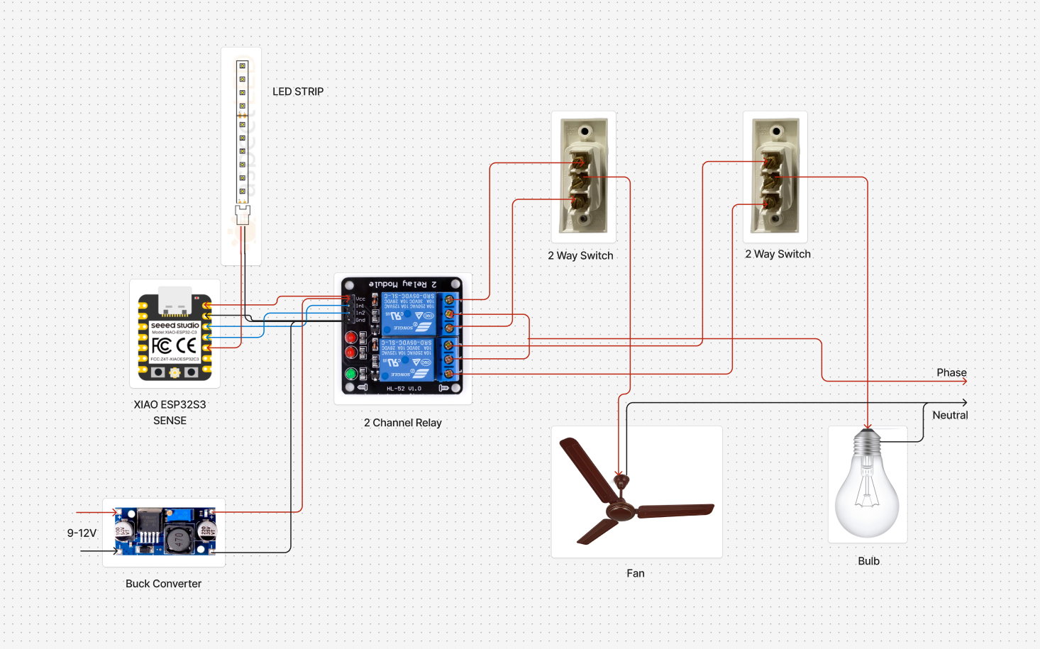
Step 4: Wiring and AssemblyThe circuit consists of the XIAO ESP32S3 sense microcontroller, a 2-channel relay module, a buck converter, and common household devices like a fan, bulb, and LED strip. A 9–12V power source is fed into the buck converter, which steps it down to 5V to power the ESP32S3 and relay module. The ESP32S3 is connected to the relay module via VCC, GND, and GPIO control pins. These control pins act as signal lines to activate the relays. The relay outputs are wired to the fan and bulb, enabling AC power to be switched on or off through the relays. Additionally, 2-way switches are connected in parallel with the relays, allowing manual control of the appliances regardless of the smart system status.
The XIAO ESP32S3 sense receives voice commands through a connected software platform or embedded voice recognition system. Based on the command, it sends HIGH or LOW signals through its GPIO pins to the relay module. When the relay receives a HIGH signal, it activates and closes the circuit, allowing AC current to flow to the respective appliance (fan or bulb). A LOW signal opens the relay, turning the appliance off. The relay acts as a bridge between the low-voltage control side (ESP32S3) and the high-voltage AC load side. The manual 2-way switches ensure that the appliances can still be operated traditionally if needed. All high-voltage connections were made carefully and securely, following proper insulation and safety practices.
Step 4: TestingThe setup was thoroughly tested to ensure reliable performance. The XIAO ESP32S3 was able to correctly recognize voice commands like “Lights On” and “Lights Off” with high accuracy. The relay switching responded quickly with almost no delay. The voice model was run completely offline on the device, so there was no need for an internet connection, which made the response time even faster.
A custom enclosure was designed in Fusion 360 to neatly house the relay module and XIAO ESP32S3 microcontroller. The design focused on practical features like ventilation for heat dissipation, easy access to ports, and mounting slots for securing the case. The look of the enclosure was also made to blend well with home interiors. The case was 3D printed using PLA material on an FDM printer and was assembled using screws for a clean and secure finish.
ADVANTAGES- Offline processing - eliminates internet dependency
- Enhanced privacy - no data sent to cloud service
- Low power consumption through Edge AI
- Faster response times compared to cloud-based systems
- Customizable and expandable system architecture
- User-friendly hands-free operation Alternative manual control option
This project showcases an efficient and scalable smart automation solution using TinyML and Google Assistant. It leverages local voice recognition for offline control and cloud integration for remote access. The approach can be extended to multiple appliances and scaled for industrial or rural automation systems.


_t9PF3orMPd.png?auto=compress%2Cformat&w=40&h=40&fit=fillmax&bg=fff&dpr=2)


Comments