


The computational electromagnetics research group at the University of Arkansas conducts research into non-destructive, non-invasive imaging applications in engineering, medical, and biological sciences. The system used is based on pulsed terahertz spectroscopy and imaging in 0.06-3THz range. Simply put the group needed a tool to allow them to control the position of a sample in a rotational and elevation manner. This is to allow a full image to be constructed through many small pulses.
ProblemThe group’s previous setup is limited to the optical table mounting points (illustrated below). The group needs a way to rotate and elevate sample for 3D imaging. This tool will increase efficiency of where to scan and allow for an image to be constructed.
Our goals for this solution were the ability to move vertically in steps ≤5µm, and rotate in increments ≤1˚. High accuracy and repeatability are important. User control via PC is preferable. We also worked to achieve these goals within the constraints of a relatively small budget which was 400 dollars.
DesignA PIC24F microprocessor was used to control the system. Communication with a PC happens via RS-232 through a MAX3232 RS-232/UART Line Driver/Receiver. The two motors are controlled by two Allegro A4988 Microstepping drivers. Both motors are identical geared stepper motors. According to the data sheet the motors should increment a quarter of a degree for every full step of the motor.
The vertical (z) motor is connected to a lead screw with 2mm pitch. Thus each full step of the motor is 1.4µm. The rotational (θ) motion is driven by a stationary motor that drives part of the assembly that rotates freely on a bearing. Each step of the motor is 1/28th of a degree. With the use of the gear ratios and microstepping the theoretical accuracy should be enough to satisfy the design goals.
A system flow diagram is shown below. The user communicates with the pic through the max232 and UART protocols. The display is shown to the user through the teraterm emulator and depending on what the user wants to do the pic will tell the motor drivers what to do. The control the pic has over the motors includes direction, sleep mode, reset, step size, enable bit, and a rising logic edge which tells the driver to step the motor once.
The major electronic parts used for the project are listed below. The Texas Instrument MAX3232CDR was chosen because it had the easier soldering part that provided a 3.3V logic level to our chosen microprocessor. The Microchip PIC24FJ256GA702-I/SP-ND was chosen because it provided the necessary number of I/O pins with an easy soldering process. It also came from Microchip which is brand that students from the electrical engineering department were familiar with. The Allegro IC MOTOR DRIVER piece was chosen due to the accuracy provided from microstepping that a bit of research had shown. The Texas Instruments IC REG BUCK 3.3V 1A 16DIP was chosen since it provided the required voltage conversion with a simple application with only 4 extra components needed. Finally the Portescap STEPPER MOTOR was chosen since it had a smaller step size due to the internally geared down output shaft.
- MAX3232CDR
- PIC24FJ256GA702-I/SP-ND
- IC MOTOR DRIVER PAR 28QFN
- IC REG BUCK 3.3V 1A 16DIP
- STEPPER MOTOR PM GEARED UNI 12V IMPLEMENTATION AND TESTING
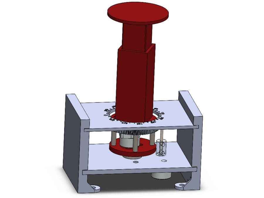
Many custom designed mechanical parts were 3D printed using ABS plastic. These are the parts depicted in red below. A slip ring was used to power the z-motor which rotates with the assembly.
To ensure accuracy of rotation, markings on the assembly were made in the 3D model which indicate the physical angle of the platform with the use of an indicator. Measurements were taken to confirm the accuracy of z-movements using a dial gauge.
The final physical PCB is shown below. Two mistakes were made during the design phase. One was a non-through hole rectangular slot for the power jack. The intended footprint was a rectangular through hole but a slot was selected and the power jack had to be surface mounted. Because of this jumper wires were needed as is shown in the bottom left-hand corner. These jumpers connected to VDD and GND. The other mistake was a wrong connection to the inductor for the buck converter. This is shown on the right side of the PCB.
When beginning the soldering process the first thing to address is ensuring the power supply works correctly. This means checking all nodes once the 12V power jack is inserted and then soldering the buck converter parts and ensuring the nodes show the expected voltage. By observing the attached PCB layout and schematic diagrams the soldering can be done in a checklist manner.
After the soldering is finished the two jumpers can be inserted to connect the programming pins of the PIC to the RJ11 jack. The code can then be uploaded using the latest version of MPLAB X IDE and a Microchip ICD3 debugger. Once the code is successfully uploaded the jumpers can be switched back to the position which would connect the PIC pins to the driver.
In order to communicate with the PIC from a PC the DB9 cable is used. This must be a straight through cable and not a null modem one. The preferred terminal emulator is TeraTerm. This is because some of the code sends out instructions that work for the TeraTerm display. Once TeraTerm is downloaded and the proper COM port has been selected the settings should be changed as such:
- Settings>Serial>(Odd Parity selected, 8 bit mode, and other options left as is)
- Settings>Keyboard>(Disable keypad application mode, leave backspace key unchecked)
- Settings>Terminal>(Check local echo, and set new line for receive and transmit both as LF)
After TeraTerm is set up hitting the reset button on the board will display the initial menu.


Comments
Please log in or sign up to comment.