It's a simple pen stand but with a twist. Every time someone removes the pen from the stand, it displays an LED animation, counts how many time pen has been removed and can also play Slot Machine game.
This project is divided into 4 parts:
- Trigger mechanism
- Enclosure
- Electronics
- Assembly
- Software
To build the trigger mechanism, we will use an acrylic tube as a pen holder into which a Pen can slide through. The acrylic tube is 2.54cm (1'') in diameter and 10.6cm (4'') in length. Two slots are cut in order to fit trigger switch.
We will use a micro-switch as a trigger. This switch has a long actuator which can be pressed even with a gentle touch, and that is what we need because some pens are very lightweight and thus cannot produce enough force to push the actuator.
Next step is to glue the micro switch and acrylic tube together, such that the actuator should pass through those two slots without touching the walls. Also, to increase the surface area, I glued a small plastic button onto the actuator.
For the enclosure, I used a ready-made Acrylic box. The dimensions are 12.7cm X 8.9cm X 15.24cm (5'' x 3.5'' x 6'') so there's enough space inside to fit all the electronics. Also, the top curved which gives it a nice look.
To install the trigger, we need to drill a hole at the top. Hole should be at either extreme left or extreme right leaving space for other components. The diameter of the hole is 2.0cm, equal to inner diameter of acrylic tube. The trigger is glued to the top from inside.
The base of this enclosure has 4 holes and two slots at the back side. The center hole is for screwing the LED matrix/Neopixel frame onto the base. Other 3 holes are for the passing wires through the inside of the base to the top.
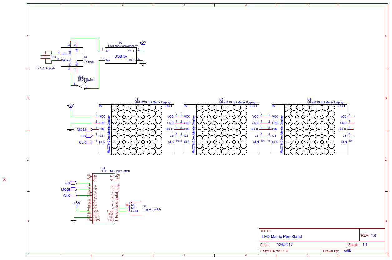
The electronic circuit is simple. The TP4056 module charges the Lipo (1500mah) and also provides an output to USB boost converter which boosts the voltage to 5v. Arduino Pro mini is powered through Vcc pins.
The ON/OFF switch is connected between TP4056's OUT pin, and USB booster's IN which allows disconnecting load while charging the Lipo.
The trigger switch is connected to Arduino's pin 2 (INT pin 0) and is pulled high using the internal pull-up resistor. So, whenever the switch is pressed (Pen is inserted), the Pin goes LOW and vice-versa. An interrupt is fired when the pin goes HIGH (Pen is removed).
I used two different modules for this project: Neopixel shield and LED matrix Modules.
- Neopixel shield:
I used an Adafruit's Neopixel shield. The shield is 5x8 matrix and it requires only 3 pins. VCC, GND and DATA pin which in this case is Arduino pin 6. The 1000uf bypass cap on the terminals to avoid sudden inrush current.
- LED Matrix Modules:
I used 3 MAX7219 LED matrix modules in cascading configuration. These modules use SPI protocol for communication.
That's pretty much it for electronics part.
Assembly:Now that we have built the trigger mechanism, enclosure, and the circuit, it's time to assemble everything.
- The TP4056 Lipo charger is aligned with the USB port slot and glued to the bottom of the base.
- The ON/OFF switch is glued to its slot.
- USB boost converter is glued onto the base and connected to Lipo charger through the two holes.
- The battery is placed at the back of the base leaving front space for LED matrix and Neopixel shield.
There are two ways of installing the Neopixel shield. For the vertical orientation (LEDs facing towards the user), I mounted the shield on a 10.6cm X 7.62cm (4''x3'') acrylic plate and used a metal L angle to screw it onto the base.
For the horizontal variation (LEDs facing upwards), I used two 45mm spacers to hold the shield above the base. The spacers are glued to the base and the PCB directly.
LED Matrix can only be installed vertically. I mounted them on the acrylic plate as mentioned above.
The entire system is interrupt driven. Every time user removes the pen an Interrupt is fired causing the Arduino to wake up from the sleep and execute the animation ISR. This code structure stays same for the both Neopixel and LED matrix programs.
Moreover, since the Arduino spends most of its time in deep sleep, we can turn off unused peripherals to save more power. For the Neopixel, I used FastLED library along with the animation examples from this GitHub repo.
For the LED Matrix, I used MD Parola library. This library provides an API for controlling each LED Matrix module independently and that's what we need for the Slot Machine program.
Conclusion:This is it! It's a fun project and a nice geeky addition to your desk.


Comments
Please log in or sign up to comment.