


Hardware components | ||||||
 |
| × | 1 | |||
 |
| × | 2 | |||
 |
| × | 1 | |||
 |
| × | 1 | |||
Software apps and online services | ||||||
| ||||||
This project is based on a project by Arduino Project Hub user Wimpie Van Den Berg
This project uses 2 potentiometers that are connected on a breadboard to an Arduino. The end result is that the values read from the potentiometers will be displayed on an Arduino IoT Cloud dashboard when they are adjusted.
You can apply the same techniques used in this tutorial to display values from any other sensor you’d like.
You will need an Arduino board that is IoT Cloud compatible, we are using the Arduino MKR WiFi 1010.
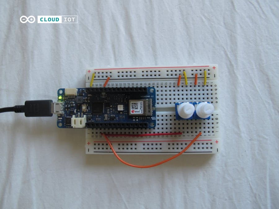
Step 1: WiringWe start by connecting all components to the breadboard, below you will find a step by step guide.
- Place the Arduino board on the breadboard.
- Place the potentiometers on the breadboard
- Connect the middle pin on one of the potentiometers to Analog input pin A1, and the other potentiometers middle pin to Analog Input pin A2.
- Connect the other potentiometer pins to power and to ground, the direction doesn’t matter.
When completed, the circuit should look like this.
To get started with this step, you will need some very basic knowledge of the Arduino IoT Cloud service. If you have built any previous project using the service, then don’t worry, you know all that you need to know.
If you are new to the Arduino IoT Cloud, then take some time to read through the Getting started page and you will be good to go. There are also a bunch of tutorials available if needed.
In the cloud, you need to create a new Thing, and configure your device and network.
You should then add two Variables. Name them “Pot1” and “Pot2”. They should be of the variable type Integer Number, and as there is no need to write any data to them from the cloud, you should limit the Variable Permission to “Read Only”
Now, you will need to create a Dashboard to see your values from your potentiometers. Go to the Dashboards section, and build a new dashboard.
Inside, create two widgets: both of them gauges.
Then you need to link them:
- Potentiometer 1> Pot1 Variable
- Potentiometer 2> Pot 2 Variable
They will for now be empty, since we have not yet uploaded the sketch to our board, which we will do in the next step.
Step 3: CodeThe code for this project is very simple, all we need to do is to read the output from the potentiometers, which can be done in just a few lines of code.
If you just want to skip ahead, the full sketch can be found at the end of this page.
The first thing that we need to do is a setup code, we declare which pins the potentiometers are connected to, by adding the following lines of code underneath the inclusion of the `thingProperties.h` file that is automatically included in your sketch.
const int potPin1 = A1;
const int potPin2 = A2;
Then, inside the setup function, we want to declare these pins as inputs. Do so by adding the following lines within the setup function
    pinMode(potPin1, INPUT);
    pinMode(potPin2, INPUT);
Now, all that is left to do is to read the values, which we do by adding two lines in the loop function
    pot1 = analogRead(potPin1);
    pot2 = analogRead(potPin2);
The full code is found below, at the end of the page.
ConclusionOnce you have uploaded this sketch, you should be able to read the values from your IoT Cloud dashboard. Enjoy!


Comments
Please log in or sign up to comment.