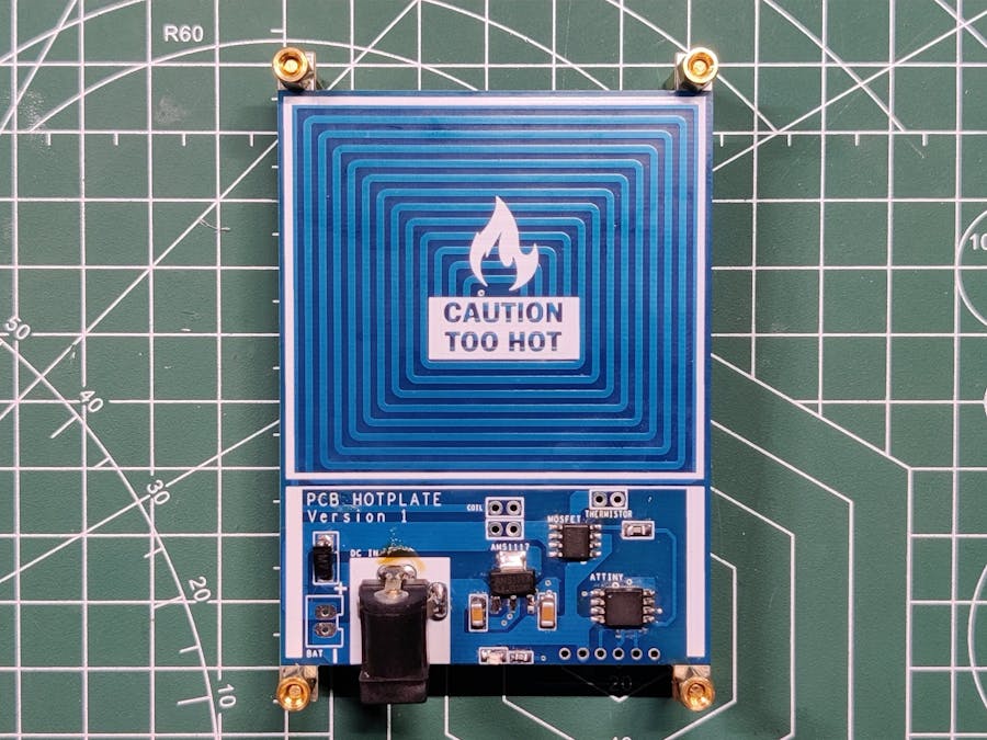
What's up, everyone? Here's something REALLY HOT: a DIY mini PCB hotplate made entirely from scratch.
The idea was to make a small and minimal reflow hotplate that could be used for SMT reflow work on small PCBs.
I previously made a huge hotplate that uses an iron element to reflow PCBs, but one problem with it is the size and lack of a temperature control system.
This version is small and has a cut-off feature that works by taking readings through a thermistor and cutting the power by turning the MOSFET off.
When powered by a 12-volt source, it can reach temperatures of up to 214 °C; the temperature can rise even higher when powered by a slightly higher voltage source.
This project is still in its infancy, so the maximum temperature and final code are not finalized yet, but it somewhat works.
There also exists a commercial mini hotplate (MiniwareMHP30), and I wanted to make a DIY version of that mini hotplate that works similarly or better than the commercial product.
This article is about the whole building process of this hotplate, so without further ado, let's get started.
Material RequiredFollowing are the materials used in this built-
- Custom PCB
- Attiny13A
- AO4406 Mosfet IC
- AMS1117 Voltage Regulator
- DC Jack
- Resistor 1K
- LED 0805 Package
- Resistor 10K
- Diode M7 SMA
- PCB Standoffs
An SMT reflow hotplate is a device that is used for soldering SMD components to the PCB by means of heat transfer.
It consists of a heating element that heats up the hotplate surface to high temperatures like 200 °C and above. PCB that is placed on the surface of the hotplate gets hot enough to reach solder paste melting temperature; as a result, solder paste melts and components get permanently attached to their pads.
Previously, I made a HOTPLATE that uses a clothed iron element as a heat source. It's been working pretty well for more than a year, but I wanted to make a miniaturized version of this device by using PCBs.
But why use PCB for this build? due to the fact that we can create coils directly on the PCB layer and use them as heating elements. Let me explain how.
As we all know, when electricity is passed through any material that has some resistance, heat is generated.
We make coils for the PCB design; these coils are essentially long copper lines, each 1mm wide. This coil has a resistance of 1.9 ohms, so if we pass electricity through it, the coil heats up, and we can use this setup as a small heating element.
Also, making a PCB design and getting it fabricated without doing any physical editing is an easy and hassle-free thing.
Attiny13AAs for the brain of this project, an Attiny13 was used because of its minimal design and low cost, making it suitable for this project. It doesn't support the existing OLED display library, so an Attiny85 could be used in the next version.
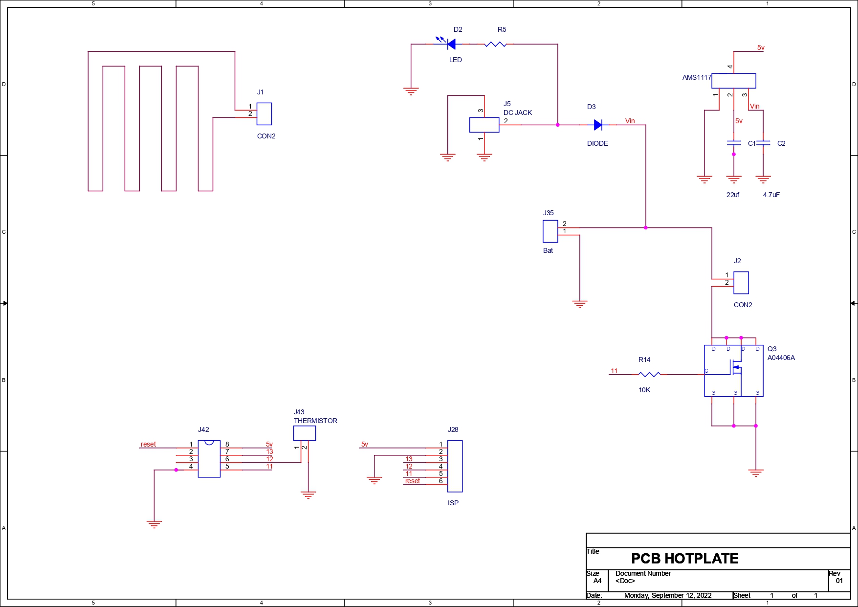
PCB DesignAs for the PCB design, we start by first preparing a schematic that consists of four main parts: the coil, microcontroller setup, mosfet as switch setup, and AMS1117 voltage regulator.
The coil was made from tracks laid out in a rectangular form factor on both layers of PCB; the track width was about 1mm.
To drive the coil, there's an N-channel Mosfet IC on the board that is connected with a minimal Attiny13 microcontroller.
Because we will be using 12V to drive the coil, an AMS1117 voltage regulator was used to drop 12V to 5V for the Attiny13 to work.
Seeed Fusion ServiceAfter finalizing the PCB and generating its Gerber data, I sent it to SEEED STUDIO for samples.
Blue soldermask and white silkscreen PCBs were ordered.
I received PCBs in a week, and their quality was super good considering the rate which was also pretty low.
Seeed Fusion PCB Service offers one-stop prototyping for PCB manufacture and PCB assembly and as a result, they produce superior quality PCBs and Fast Turnkey PCBA within 7 working days.
This hotplate PCB quality was AMAZING!
Seeed Studio Fusion PCB Assembly Service takes care of the entire fabrication process, from PCB manufacturing to parts sourcing, assembly, and testing services, so you can be sure that you are getting a quality product.
After gauging market interest and verifying a working prototype, Seeed Propagate Service can help you bring the product to market with professional guidance and a strong network of connections.
Next, we prepare for the PCB assembly process.
PCB AssemblyThe PCB assembly process will have the following steps:
- Solder Paste Dispensing
- Pick & Place Process
- Hotplate Reflow
- THT Components
The first step is to apply solder paste to each component pad.
We use regular Sn-Pb solder paste that has a melting temperature of 140° to 270°C, and to apply the solder paste, a solder paste syringe with a wide nozzle is used.
Pick and Place ProcessWe then used an ESD tweaker to carefully pick and place all the SMD components in their assigned places one by one, which took like 30 seconds tops, but the result was a perfect PCB with all the components placed in their locations.
Hotplate ReflowAfter the "pick and place process, " we carefully lifted the whole circuit board and placed it on my DIY SMT Hotplate which is also homemade just like this project.
After a few minutes, when the hotplate reaches the solder paste melting temperature, this hot reflow process will solder all of the components.
Adding THT ComponentsNext, we add a DC barrel jack to this circuit and use a regular soldering iron to solder it in its place.
PCB StandoffsTo finally complete this board, we added PCB standoffs to all four sides of the board.
PCB standoffs lift the circuit and act as a stand for the board.
Attiny13A ProgrammingAttiny13A is an AVR MCU that can be flashed via an ISP programmer like USBASP, or we can make a simple ISP programmer by using an Arduino Uno or Nano board.
- We go to Example sketches> Arduino as ISP and upload it into the Arduino Nano board.
- Next, we add a 1uf Capacitor between RST and GND Pin, this will stop Arduino to reset during the flashing process (Add capacitor after uploading the Arduino as ISP Sketch)
- Now go to this link and download the Attiny13 Core files- https://github.com/MCUdude/MicroCore
- Next, we wire Attiny13A's SPI Pins with Arduino Pins according to the attached wiring diagram.
- we then go to tools and change the MCU and choose Attiny13.
- We select the right port and change the programmer to "Arduino as ISP"
- Next, we click on Burn Bootloader, if the wiring is correct, you will see a "Done burning Bootloader" message.
- At Last, we go to the sketch menu and select "upload using programmer" and the board will get flashed with the sketch which was opened at that moment.
For flashing the MCU, I used my existing AVR Flasher which Is an Arduino Nano that runs Arduino as an ISP sketch.
CODE
Here's the main code I used-
int ThermistorPin = 1;  //Thermistor Pin
const int RelayPin = 0; //Mosfet Pin
const int threshold = 215;  //Stopping temp

int Vo;
float R1 = 100000;
float logR2, R2, T, Tc;
float c1 = 1.009249522e-03, c2 = 2.378405444e-04, c3 = 2.019202697e-07;

void setup() {
pinMode(RelayPin, OUTPUT);
pinMode(ThermistorPin, INPUT);
Serial.begin(9600);
}

void loop() {

  Vo = analogRead(ThermistorPin);
  R2 = R1 * (1023.0 / (float)Vo - 1.0);
  logR2 = log(R2);
  T = (1.0 / (c1 + c2*logR2 + c3*logR2*logR2*logR2));
  T = T - 273.15;

  Serial.print("Temperature: ");
  Serial.print(T);
  Serial.println(" C");

  delay(500);

 if (Tc > threshold) {
    digitalWrite(RelayPin, LOW);
  } else {
    digitalWrite(RelayPin, HIGH);
  }

}
Please note that the sketch is not completely finalized and takes wrong readings; however, the heating part is working properly.
Test #1- Max Temperature ReachedThe hotplate's onboard thermistor isn't working properly, so I added an external temperature sensor for measurement.
After turning on the hotplate, the temperature slowly increases until, after a few minutes, it reaches the maximum temperature of 214 °C, which is crazy hot.
This temperature can be further increased if we increase the voltage fed to the coil.
A 12V SMPS is being used here.
Test #2- Reflowing Small PCB- For the actual test, we take a small PCB and add solder paste to the component pads.
- next, we pick and place the components on the Test PCB.
- At last, we add the Test PCB on Reflow Hotplate and wait for a couple of minutes.
The PCB hotplate melts the solder paste, and components get the solder to their pads properly.
While working with this setup, I recommend using lower-temperature solder paste; I'm using normal solder paste that requires a temperature between 180 and 200 °C, but solder paste with a melting temperature of 150 to 180 °C could work better.
Result and ConclusionThe PCB hotplate works, and it's able to solder a small board with no major issues.
There are some things that need improvement and major remodeling.
We first have to improve the temperature measurement unit on this board. I'm thinking about using a proper temperature sensor this time that is capable of measuring temperatures up to 500°C.
As for design, we need an OLED screen to measure the current temperature.
Version 2 will include these two items as well as an improved body; this version served as a concept.
Overall, I'm pretty happy with the result. This hotplate is small and so inexpensive that why would we ever want to buy an overpriced hotplate when we can create our own that can easily rival the actual product?
If you need any help regarding this project, do leave a comment.
Thanks for reading this article, and I will be back with a new project soon.
Peace.


_LWNORVejBN.png?auto=compress%2Cformat&w=48&h=48&fit=fill&bg=ffffff)


Comments
Please log in or sign up to comment.