


Hardware components | ||||||
 |
| × | 1 | |||
 |
| × | 1 | |||
Good day, and welcome back.
Pika Bank is an interesting power-related project. A portable 5V power source called Pika Bank is designed to power 5V devices including microcontrollers, DEV boards, smartphones, and other similar devices.
The name PIKA is a play on the name of the well-known anime character Pikachu from the Pokemon series. Thunderbolt is one of Pikachu's attacks, and he is an electric-type Pokemon. This device is similar and can supply a steady voltage for the operation of XYZ 5V devices.
It functions essentially as a powerbank because it has an IP5306 IC, a power management IC that is frequently used in commercial powerbank circuits.
This article is about the construction of this powerbank, so let's start with the built.
Materials RequiredThe following are the materials used in this built:
- Custom PCBs
- IP5306 IC
- 1uF 0805 Package Capacitors
- 2R 1206 Package Resistors
- 1uH Inductor
- USB Port
- USB Type C
- SMD 18650 Cell Holder
- BLUE 10mm LEDs
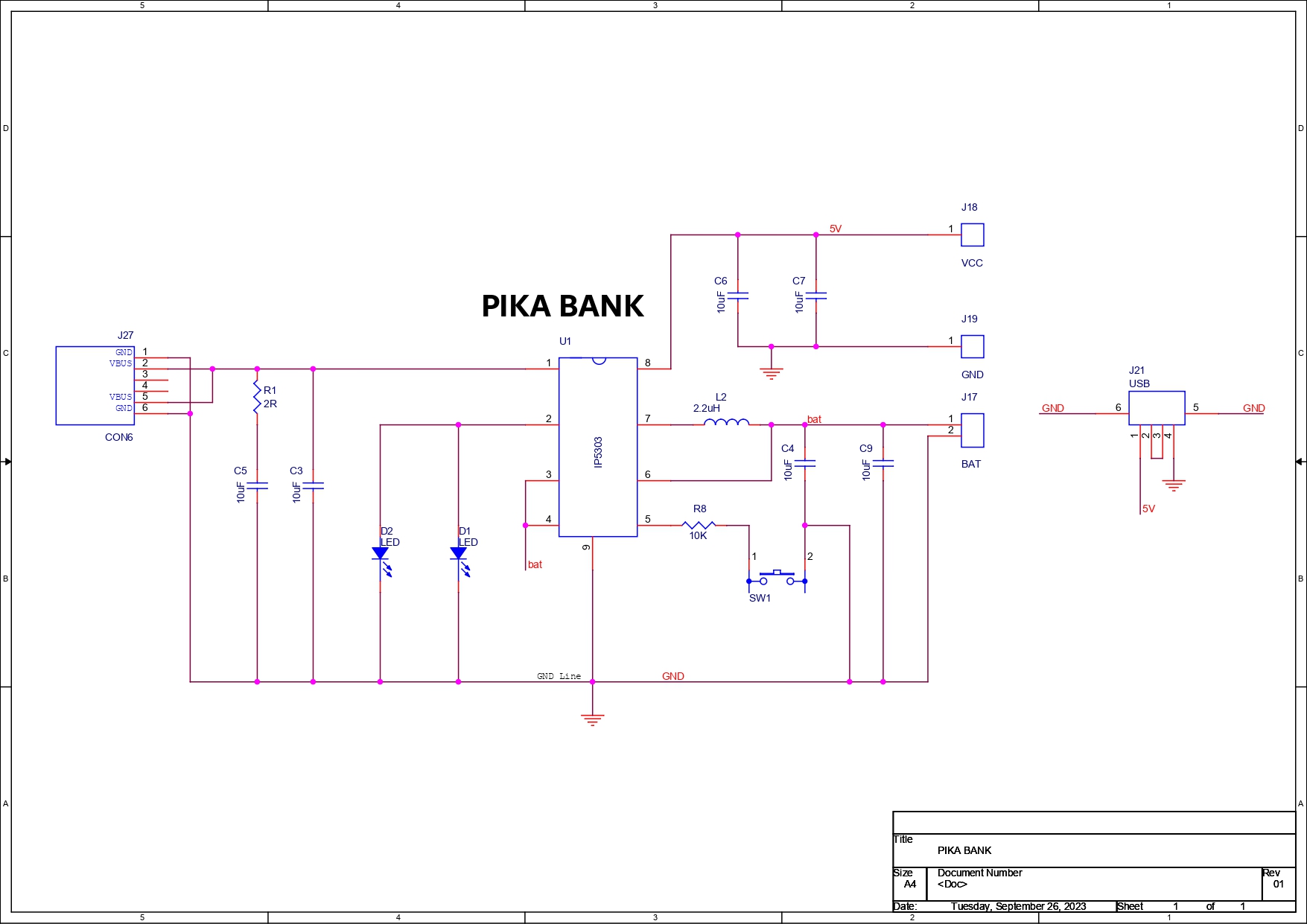
In order to power a range of 5V-operated devices, we start by designing the schematic for the PCB, which includes the IP5306 IC, a power management IC with a 3.7V input and a stable 5V output.
I have used this IC in many of my previous projects, which you can check out here-
https://www.hackster.io/Arnov_Sharma_makes/cone-lamp-with-xiao-211fed
https://www.hackster.io/Arnov_Sharma_makes/xiao-room-temp-and-humidity-meter-00c4af
https://www.hackster.io/Arnov_Sharma_makes/overengineered-pen-holder-2-0-5c0daf
The IP5306 IC is placed first in the schematic, along with a few capacitors between charging IN and GND on the input side and a few between the 5V pin and GND on the output side.
A 18650 battery holder, a type C port for charging, and a USB port for 5V output are all placed on the bottom side of the PCB.
Moreover, two 10mm LEDs have been added to the board's top side, near the pickachu's cheek.
The design was finalized and then sent to PCBWAY for samples.
PCBWAY ServicePCBWAY provided the PCBs for this project; we uploaded the Gerber data to their PCB Quote page and placed an order for yellow solder masks with white silkscreen.
We received the PCBs in less than a week, which was extremely fast, and the quality was excellent as usual.
I've been using their service for a while now, and it's always excellent.
Check out PCBWAY for great PCB service at a low cost.
Solder paste Dispensing ProcessUsing a solder paste dispensing needle, we first apply solder paste to each component pad. The standard 63/37 Sn/Pb solder paste ratio is being applied.
Pick and Place ProcessFollowing the application of solder paste, each component is added one at a time using an ESD tweezer; in this case, all of the capacitors, inductors, integrated circuits, and resistors are positioned where they are supposed to be.
Reflow StationFor the reflow process, we employ a hot air station that blows hot air at a temperature greater than 300 degrees Celsius, melting the solder paste and permanently securing the components to their pads.
Adding Type C PortAfter adding SMD components on the top side of the PCB, we move on to adding components on the bottom side.
We begin by first applying solder paste with the solder paste dispensing needle on the Type C USB pads.
After that, we use the hot air station to solder the USB port into location.
THT ComponentsUsing a soldering iron, we attach the THT components—the USB Port and the Lithium Cell 18650 Holder—on the bottom side of the device after attaching the Type C Port.
After using a soldering iron to secure the 10mm LEDs in place from the TOP side of the PCB, we remove the extra leads from the LEDs.
The circuit is now ready.
Power Source and TestingA 3.7V, 2900mAh lithium cell is being used to power this whole setup.
We place the lithium cell in its SMD Holder in the correct polarity and press the toggle switch once to turn on the 10mm LED, indicating that the circuit is operational.
The output voltage was then tested with a multimeter, and 5.1V was observed.
After the voltage measurement, we use a USB tester to measure the voltage through the USB port and find 5.1V there as well.
After measuring the voltage, we use a USB tester to check the voltage coming from the USB port and discover that it is also 5.1V.
Powering an ArduinoNow that this circuit is working, we can now use it to power any MCU that requires 5 volts.
In order to verify this, we connect jumper wires to the Pika Bank's output terminals and connect them to the VCC and GND terminals of an Arduino Nano.
Below is the code that was used; the LED and Blink Sketch are connected to the Nano's D2 Pin.
void setup() {
  // initialize digital pin LED_BUILTIN as an output.
  pinMode(2, OUTPUT);
}

// the loop function runs over and over again forever
void loop() {
  digitalWrite(2, HIGH);   // turn the LED on (HIGH is the voltage level)
  delay(1000);                       // wait for a second
  digitalWrite(2, LOW);    // turn the LED off by making the voltage LOW
  delay(1000);                       // wait for a second
}
The setup was successful once the program was uploaded to an Arduino Nano and the MCU was powered by a Pika Bank. As a result, we may utilize this device to power projects like these.
Running Raspberry Pi through Pika BankIn order to power the Raspberry Pi Model 4B, we connect a Type C cable to the USB port, and it turns on as well.
Charging SmartphoneAt last, we connect a smartphone with the Type C cable, and it charges as well.
It should come as no surprise that the IP5303 utilized in this project can be used as a mobile charger or a reliable 5V power supply since it is originally a Power management IC that is frequently used in commercial power banks.
Conclusion
Overall, this arrangement is functional and capable of powering a variety of devices, including an Arduino board and a mobile phone. For the majority of gadgets, it can supply stable 5V output. The system can only output a maximum current of 2A, which is fine in most situations but not if we wish to drive more powerful devices like an LCD display or LED matrix.
Thanks for getting this far; please leave a comment if you need any help with this project.
Special thanks to PCBWAY for supporting this project; do check them out for great PCB service at a lower cost.
Thanks again, and I will be back with a new project soon.


Comments
Please log in or sign up to comment.