Greetings and welcome back.
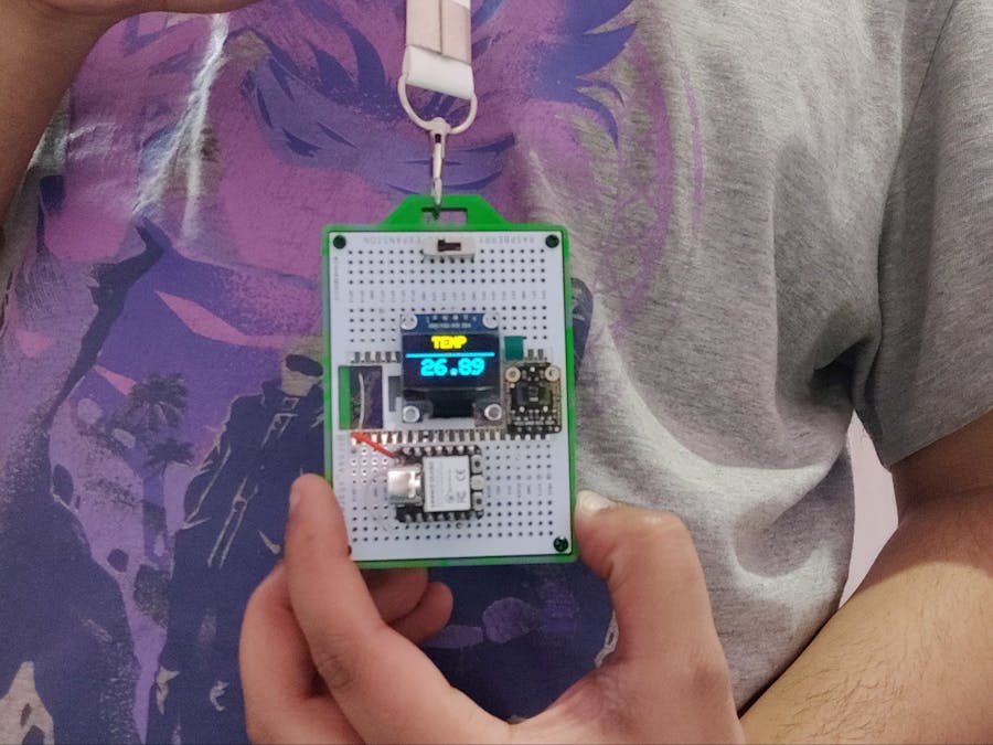
Here's something cool: The TEMPERATURE CARD The project is a wearable ID card-like device that has an OLED screen that displays live temperature readings taken from the SHT40 temperature sensor module.
The heart of this project was an XIAO ESP32C3 development board, which is paired with an SSD1306 display. An SHT40 TEMP sensor is being used for temperature data, and the whole setup is powered by a small 3.7V LiPo cell that is connected directly to the XIAO ESP32C3 board's battery terminals.
The whole device was made in two stages: the first was the breadboard version, and the second was on a prototyping board, which was then encased in a 3D-printed body.
The whole article is about the build process of this project, so let's get started with the build.
Materials RequiredThese were the components used in this project:
- XIAO ESP32C3 DEV Board
- SHT40 TEMP SENSOR
- SSD1306 Display
- Custom Prototyping Board
- 3D-printed parts
- Silver-copper wire
- breadboard
- jumper wires
- Slide switch
- M2 Screws
In this project, we are using the XIAO ESP32C3, which is a IoT mini-development board based on the Espressif ESP32C3 WiFi/Bluetooth dual-mode chip. ESP32-C3 is a 32-bit RISC-V CPU, which includes an FPU (Floating Point Unit) for 32-bit single-precision arithmetic with powerful computing power.
This board comes with an external antenna to increase the signal strength for wireless applications. It also has a small and exquisite form-factor combined with a single-sided surface-mountable design.
It is equipped with rich interfaces and has 11 digital I/O that can be used as PWM pins and 4 analog I/O that can be used as ADC pins. It supports four serial interfaces, such as UART, I2C and SPI. There is also a small reset button and a bootloader mode button on the board.
The battery connector on the backside of the DEV board will be used in this project to add a LiPo cell to power the XIAO as well as the display and SHT40 sensor.
You can check out Seeed Studio's brief product introduction for the XIAO ESP32C3, which includes a ton of information, by clicking the link below.
https://wiki.seeedstudio.com/XIAO_ESP32C3_Getting_Started/
Visit Seeed Studio Fusion to get a wide range of services, including 3D printing, PCB/PCBA, and microcontroller/module services.
https://www.seeedstudio.com/fusion_pcb.html
Breadboard VersionWe first started with a simple breadboard version that included the three main components used, which are the XIAO ESP32C3 board, the SSD1306 screen, and the SHT40 temperature sensor.
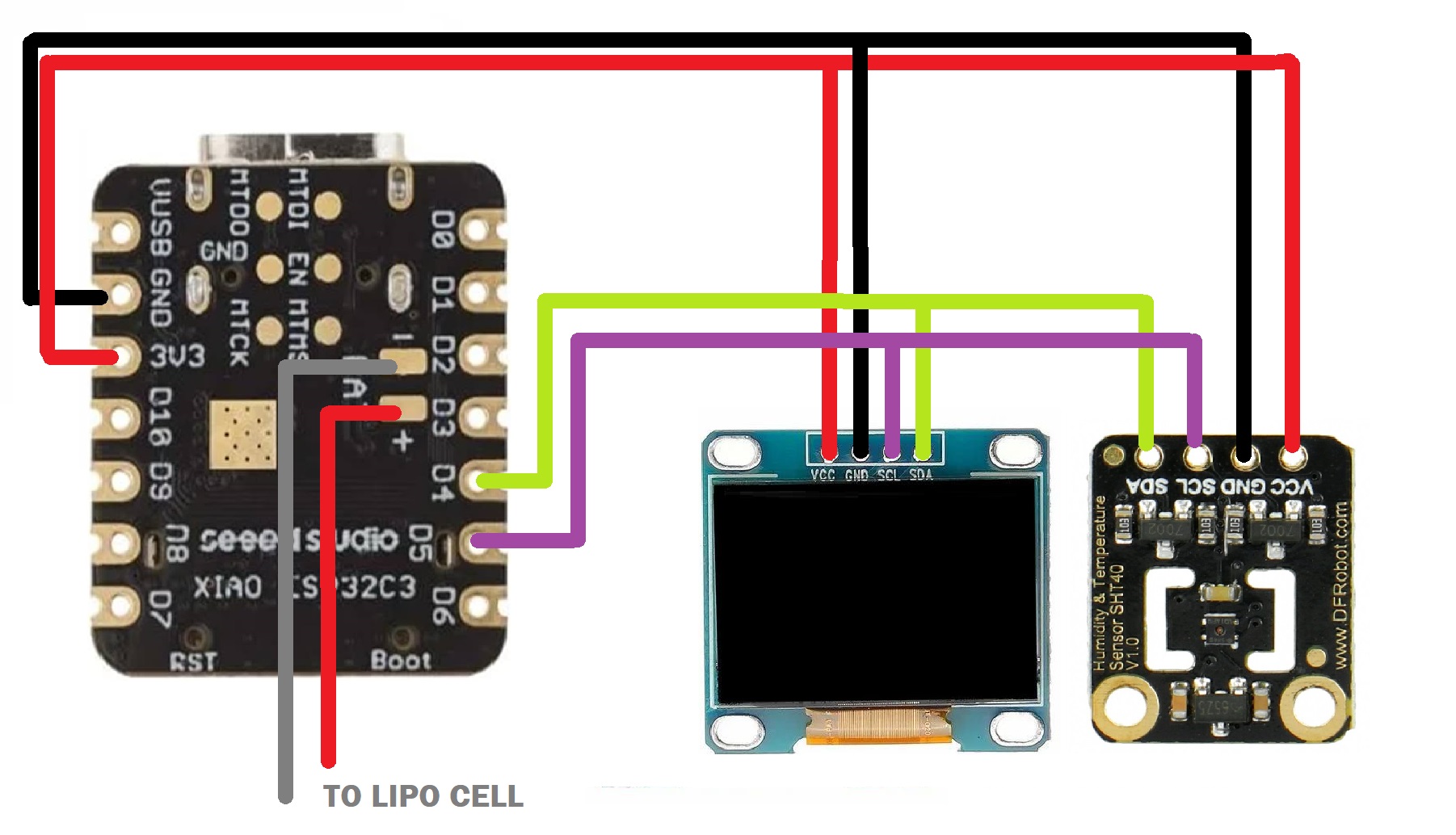
- We added them to a breadboard and first connected the 3V3 pin of XIAO with SHT40's VCC and SSD1306 Screen's VCC port.
- Next, we connect the GND of XIAO with SHT40 and SSD1306's GND Port.
- We then add the A4 Pin of XIAO to the SDA pins of SHT40 and SSD1306.
- At last, we add the A5 Pin of XIAO to the SCK pins of SHT40 and SSD1306.
Here's the code that was used in this build, and its a simple one.
#include "Adafruit_SHT4x.h"
#include <Wire.h>
#include <Adafruit_SSD1306.h>
#include <Adafruit_GFX.h>

#define OLED_WIDTH 128
#define OLED_HEIGHT 64

#define OLED_ADDR   0x3C

Adafruit_SHT4x sht4 = Adafruit_SHT4x();

Adafruit_SSD1306 display(OLED_WIDTH, OLED_HEIGHT);

void setup(){
Serial.begin(115200);

display.begin(SSD1306_SWITCHCAPVCC, OLED_ADDR);
display.clearDisplay();

Serial.println("Adafruit SHT4x test");
  if (! sht4.begin()) {
    Serial.println("Couldn't find SHT4x");
    while (1) delay(1);
  }
  Serial.println("Found SHT4x sensor");
  Serial.print("Serial number 0x");
  Serial.println(sht4.readSerial(), HEX);

  sht4.setPrecision(SHT4X_HIGH_PRECISION);
  switch (sht4.getPrecision()) {
     case SHT4X_HIGH_PRECISION:
       Serial.println("High precision");
       break;
     case SHT4X_MED_PRECISION:
       Serial.println("Med precision");
       break;
     case SHT4X_LOW_PRECISION:
       Serial.println("Low precision");
       break;
  }

  // You can have 6 different heater settings
  // higher heat and longer times uses more power
  // and reads will take longer too!
  sht4.setHeater(SHT4X_NO_HEATER);
  switch (sht4.getHeater()) {
     case SHT4X_NO_HEATER:
       Serial.println("No heater");
       break;
     case SHT4X_HIGH_HEATER_1S:
       Serial.println("High heat for 1 second");
       break;
     case SHT4X_HIGH_HEATER_100MS:
       Serial.println("High heat for 0.1 second");
       break;
     case SHT4X_MED_HEATER_1S:
       Serial.println("Medium heat for 1 second");
       break;
     case SHT4X_MED_HEATER_100MS:
       Serial.println("Medium heat for 0.1 second");
       break;
     case SHT4X_LOW_HEATER_1S:
       Serial.println("Low heat for 1 second");
       break;
     case SHT4X_LOW_HEATER_100MS:
       Serial.println("Low heat for 0.1 second");
       break;
  }

}

void loop() {

 sensors_event_t humidity, temp;

  uint32_t timestamp = millis();
  sht4.getEvent(&humidity, &temp);// populate temp and humidity objects with fresh data
  timestamp = millis() - timestamp;

  display.clearDisplay();          //TEMP
  display.setTextSize(2);
  display.setTextColor(WHITE);
  display.setCursor(38, 0);
  display.println("TEMP");

//  display.display();


  display.setTextSize(1);                 //TEMP VALUE
  display.setTextColor(WHITE);
  display.setCursor(0, 20);
  display.println("---------------------");

  display.display();


  display.setTextSize(3);                 //TEMP VALUE
  display.setTextColor(WHITE);
  display.setCursor(22, 30);
  display.println(temp.temperature);
  display.display();
  delay(10);

}
This sketch interacts with two sensors: the SHT4x temperature and humidity sensor and the SSD1306 OLED display, and the code essentially reads the temperature from the sensor and displays it on the OLED screen. It could be further extended to include humidity readings or additional functionalities
Make sure to download and install SHT40's Library and SSD1306 Library before uploading this sketch.
https://github.com/adafruit/Adafruit_SHT4X
https://github.com/adafruit/Adafruit_SSD1306
LEVEL 2: AssemblyHere is the level 2 of this project, which included making a custom circuit board to actually make the device small and useful after working on the breadboard version.
we are using a custom prototyping board, which I made for a previous raspberry pi pico project.
https://www.hackster.io/Arnov_Sharma_makes/raspberry-pi-pico-as-hid-mouse-370827
- We start by first adding all three boards to the prototyping board in the correct order: the SSD1306 display in the middle, the XIAO DEV board on the bottom side, and the SHT40 on the right side next to the SSD1306 display.
- Next, we turn the PCB around and solder all the pads of all three boards using a soldering iron.
- We now make connections, and for that, we are using silver copper wire.
- Using the same silver copper wire, we connect the VCC of the SHT40 and SSD1306 to XIAO's 3V3 pin. Next, we add the GND of all three together. Finally, we connect XIAO's I2C pins A4 and A5 to the SCL and SDA pins of the SHT40 and SSD1306 module.
The XIAO ESP32C3 microcontroller has two battery connectors on the back for integrating the battery with the device. It also has an integrated lithium cell charging IC that enables us to attach a small lipo cell to power the entire device.
To pair the LiPo Cell with the Temp Card Setup, we first soldered two wires to XIAO's battery terminals.
Next, we add XIAO to the header pins and connect the previously added two wires to two different solder points on the prototyping board.
Then, we soldered the two wires that were previously added to the battery. In addition, we used a slide switch that is connected to the battery's GND and the negative terminal of the microcontroller's battery terminal. The device can be turned on or off with this switch.
3D DesignIn order to create a 3D design, we first use Fusion360 to model the entire circuit board. After that, we build an enclosure to enclose the PCB outline and set the circuit on top of the model. Four mounting holes are created to ensure the circuit stays in place.
For mounting the battery from below, we added a compartment like portion, which keeps the battery intact and secure.
Additionally, we added a slotted part on the top face of the model, which will be used to connect an ID card strap to the body.
Once the design was finished, we exported the mesh file and used a green PLA material to 3D print it using an Ender 3 printer with a 0.4mm nozzle and 25% infill.
FINAL ASSEMBLYThe final assembly was quite easy. We just placed the circuit on top of the 3D printed model and used four M2 screws to firmly attach the enclosure to the entire circuit.
RESULTHere's the result of this simple build: a working temperature meter based around the SHT40 and XIAO ESP32C3 development boards.
We added an ID card strap to the 3D-printed enclosure, which allows the user to wear this device as a digital ID card that shows temperature readings.
By using the slide switch, the user can turn the device on or off, and portability was possible because of the small LiPo cell that was used to power this device.
I have made a couple of different temperature meter projects, which you can checkout at the below links if you're interested in this topic.
https://www.hackster.io/Arnov_Sharma_makes/pocket-temp-meter-4b0119
https://www.hackster.io/Arnov_Sharma_makes/diy-thermometer-with-ttgo-t-display-and-ds18b20-v2-2f210c
https://www.hackster.io/Arnov_Sharma_makes/live-temp-meter-with-xiao-and-aht10-c482ea
https://www.hackster.io/Arnov_Sharma_makes/max6675-temp-sensor-with-xiao-m0-6bc5f7
Level 3 of this project will include a bigger screen and a custom PCB, which will house more electronics in a more compact formfactor. Stay tuned for that.
Leave a comment if you need any help regarding this project. This is it for today, folks.
Thanks to Seeed Studio Fusion for supporting this project.
You guys can check them out if you need great PCB and stencil service for less cost and great quality.
And I'll be back with a new project pretty soon!


_LWNORVejBN.png?auto=compress%2Cformat&w=48&h=48&fit=fill&bg=ffffff)


_t9PF3orMPd.png?auto=compress%2Cformat&w=40&h=40&fit=fillmax&bg=fff&dpr=2)


Comments
Please log in or sign up to comment.