Hi,
so you have used Neopixel Rings/Strips/Matrix in one of your projects and now you want to make a circuit and add WS2812B LED on it but don't know-how?
then this post is just for you!
WS2812B is an intelligent control LED light source that the control circuit and RGB chip are integrated into a package of 5050 components. It internal include intelligent digital port data latch and signal reshaping amplification drive circuit.
The data transfer protocol uses a single NZR communication mode. After the pixel power-on reset, the DIN port receive data from controller, the first pixel collects initial 24bit data then sent to the internal data latch, the other data which reshaping by the internal signal reshaping amplification circuit sent to the next cascade pixel through the DO port. After transmission for each pixel, the signal to reduce 24bit. pixel adopt auto reshaping transmit technology, making the pixel cascade number is not limited the signal transmission, only depend on the speed of signal transmission.
well, read its datasheet for more info- datasheet
Materials required- ws2812B
- Custom PCBs (which were provided by JLCPCB)
- NodeMCU 12E
- 0.1uf 0603 capacitor
you can buy WS2812 from utsource.net
STEP 1Step 1 of using WS2812B would be to make a breakout board PCB so we can solder them on the PCB and use it with any Microcontroller.
They work according to this pinout connecting diagram
This Schematic can be used when making any WS2812B based LED strip or matrix, just remember this, the Dout of the first LED goes into Din of the second LED, and the Dout of the second LED goes to Din of the Third LED and this goes on and on.
also, it's mandatory to add an 0.1uf Capacitor to the VCC and GND of each WS2812B.
and it is recommended to only supply them with a voltage between 3.3V to 5V.
"in order to use WS2812B, we just need to hook them up with a microcontroller in this way along with 0.1uf Capacitor"
so I made this schematic and prepared a PCB which have the same WS8212B setup connected with an Attiny85 Microcontroller. (this is for the custom PCB, the attiny85 part)
you can check out that project here-
I basically followed this approach/process and made this circuit in OrCad Cadance and send it to JLCPCB for PCB samples.
I have to say, the samples that I got were GREAT AS ALWAYS!
(This PCB is designed in such a way that if I don't short the Resistance marked on the above picture, the Din of First LED won't get connected via Attiny so this will work like a normal LED strip, so I connected it with a NodeMCU instead because its easy to program a NodeMCU in compare with an Attiny85 lol)
The soldering Process was basically this-
Also, you gonna need an SMT blower or a Hotplate in order to solder these LED on custom PCBs.
unfortunately, I don't have those stuff so I made my own SMT hotplate with an Iron Element and a big copper plate, it works like a proper SMT hotplate so you just need to add solder paste to the pads of ws2812B like this, Place WS2812B on its assigned pad facing the right way and let the heat do the rest of trick.
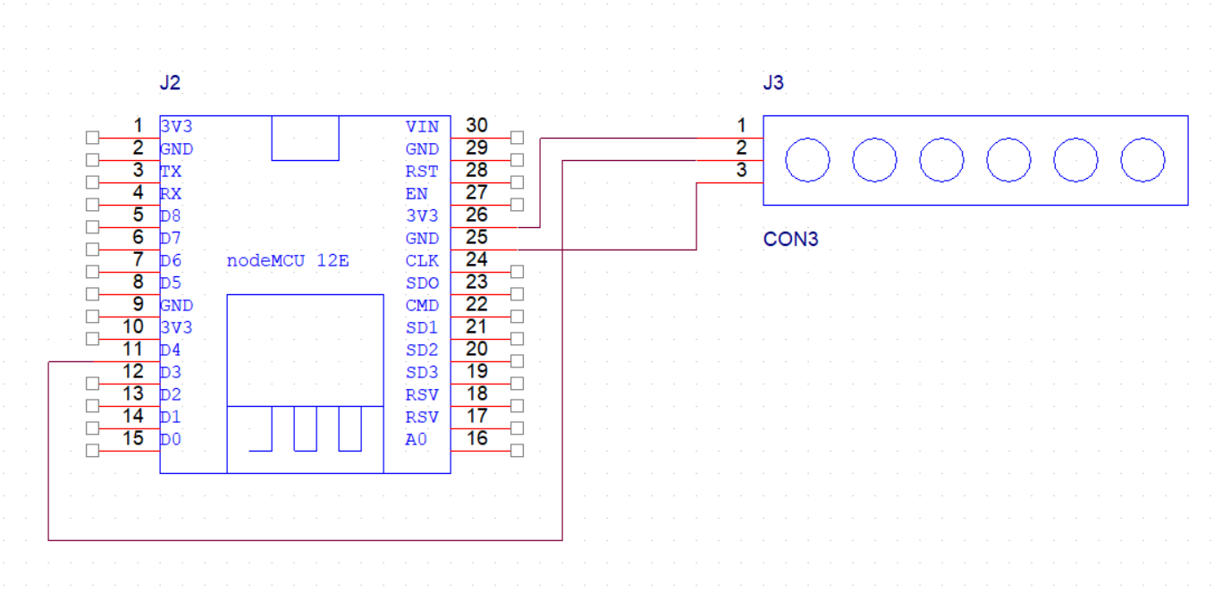
well for simplicity, I hooked a NodeMCU with a custom RGB Strip that I made instead of driving it with attiny85, according to this Pinout-
- VCC of LED to 3v3
- GND to GND
- Din of LED to D4
I used this code (Neopixel Rainbow) which is like a Blink sketch of WS2812B
first, download and install this library- https://github.com/adafruit/Adafruit_NeoPixel
now open the sketch attached
we need to change a few parameters though.
we have to specify the number of LEDs that we are using which would be 6 in my case and then change the Pin according to whatever MCU are you using... I'm using NodeMCU's D4 pin. so pixel pin 2
RESULTAttiny85 setup-
WS2812B Setup-
I hope you have learned some basic stuff about WS2812B LED and now can use them in projects without any problem.
If you guys need any help, just message me or leave a comment!


Comments
Please log in or sign up to comment.