


Hardware components | ||||||
 |
| × | 1 | |||
Software apps and online services | ||||||
 |
| |||||
Hand tools and fabrication machines | ||||||
_LWNORVejBN.png?auto=compress%2Cformat&w=48&h=48&fit=fill&bg=ffffff) |
| |||||
Hey everyone, what's up?
Hey here's something helpful: a home automation shield designed for Seeed XIAO DEV boards with a single SPDT relay and inbuilt AC-DC power so we can run this board directly off an AC source.
It works with all XIAO boards, including the ESP32 C3 XIAO and the most recent ESP32 S1 XIAO.
This project is about how this simple home automation board was made and how you can use it for controlling XYZ loads, so let's start with the building process.
Material RequiredThese were the components used in this project.
- Seeed XIAO DEV Board
- Custom PCB
- SPDT 5V Relay
- Isolated Power supply 240V AC to 5V DC
- M7 Diode
- AO3400 N Channel mosfet
- 10K Resistors
The Seeed Xiao is a series of development boards that provide a compact and versatile platform for prototyping and building electronic projects. The Xiao boards are designed by Seeed Studio and come in different versions, each catering to specific requirements and functionalities.
The original Seeed Xiao board features an ARM Cortex-M0+ microcontroller and offers a rich set of I/O pins, including digital, analog, and specialized communication pins. It also has a built-in micro USB port for programming and power supply. Additionally, Seeed has released variants such as the Seeed Xiao Lite, which is a smaller and more affordable version, and the Seeed Xiao RP2040, which is based on the Raspberry Pi RP2040 microcontroller and offers enhanced processing power and connectivity options.
The newest XIAO ESP32S3 Sense from SEEED was just released; it features the ESP32S3 32-bit dual-core Xtensa processing chip, as well as an inbuilt camera module and a digital microphone.
Regardless of the version, Seeed Xiao development boards are popular choices among hobbyists, makers, and professionals alike due to their compact form factor, extensive I/O capabilities, and ease of use for a wide range of projects.
This project will utilize the XIAO M0 and XIAO ESP32 C3.
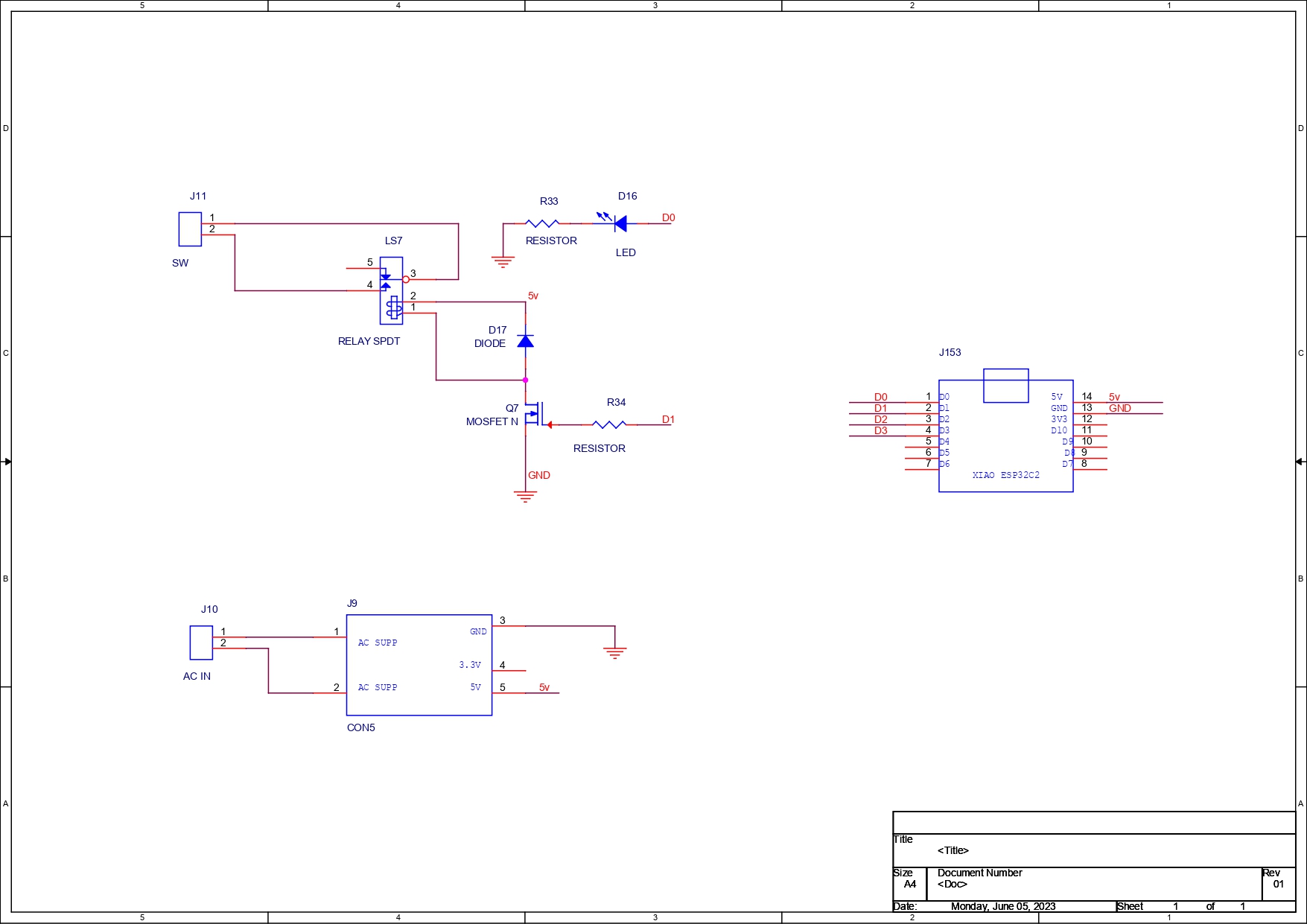
PCB SchematicThis board's PCB schematic, which is a straightforward one, was initially created.
This circuit board has a mosfet configured as a switch that is connected to an SPDT relay. The mosfet's gate is connected to the XIAO D1 pin through a 10K resistor. In addition, the XIAO's GND and D0 pins are both connected to an LED.
The power supply's 5 volt output is attached to an XIAO and relay configuration, and there is also an isolated SMPS that is connected to a CON2 port and will be used to power this supply via an AC source.
The board's schematic was converted into a PCB design when it was finished.
A board outline was created, with a relay and an isolated power supply on one side and XIAO on the other.
For aesthetic reasons, we put a round silkscreen to the PCB. Then, we produced the gerber data and sent it to Seeed Studio for samples.
Seeed Studio Fusion ServiceAfter finalizing the PCB and generating its Gerber data, I sent it to SEEED STUDIO for samples.
PCB was ordered in Blue solder mask with white silkscreen.
PCBs were received in a week, and their quality was super good considering the rate, which was also pretty low.
Seeed Fusion PCB Service offers one-stop prototyping for PCB manufacture and PCB assembly, and as a result, they produce superior quality PCBs and fast turnkey PCBAs within 7 working days.
PCB Quality of this HOMEAUTOMATION SHIELD WAS SUPER!
Seeed Studio Fusion PCB Assembly Service takes care of the entire fabrication process, from Seeed Studio Fusion Agile manufacturing and Hardware Customization to parts sourcing, assembly, and testing services, so you can be sure that they are getting a quality product.
After gauging market interest and verifying a working prototype, Seeed Propagate Service can help you bring the product to market with professional guidance and a strong network of connections.
Next is the PCB assembly process.
PCB Assembly- Board Assembly Process begins by first adding solder paste to each component pad one by one.
- Next, using a tweezer, we pick and position each SMD component in its designated location.
- Following that, we carefully lifted the entire circuit board and set it down on the SMT Hotplate, which heats the PCB from below up to the solder paste melting temperature. As soon as the PCB reaches that temperature, the solder paste melts, and all the components are connected to their pads.
- Next, we add all the THT components, which include the relay, header pin, CON2 connector, and isolated power supply, to their locations and then solder their pads using a soldering iron.
The circuit is now complete.
CODEHere's the main sketch for this project, a web server sketch that I modified from my previous home automation project; even the web page title is from that project, and it's easily changed by changing the lines below.
This sketch uses the XIAO ESP32 C3 board.
client.println("<body><h1>HOME AUTOMATION DUAL OUTPUT</h1>");- Copy this sketch and change the SSID and password before uploading it to the XIAO DEV Board; this setup will also work with any ESP32 or ESP8266 boards.
- After uploading the sketch, we open the serial monitor and allow the ESP to connect to the local WIFI. Once connected, you will see its IP address in the serial monitor.
- Copy the IP Address and open it into any browser which will let you access the Web page for controlling the RELAY.
#include <WiFi.h>

// Replace with your network credentials
const char *ssid = "Your SSID";
const char *password = "Your PASS";

// Set web server port number to 80
WiFiServer server(80);

// Variable to store the HTTP request
String header;

// Auxiliar variables to store the current output state
String output1State = "off";


// Assign output variables to GPIO pins
const int output1 = 2;


void setup() {
  Serial.begin(115200);
  // Initialize the output variables as outputs
  pinMode(output1, OUTPUT);
  digitalWrite(output1, LOW);

  // Connect to Wi-Fi network with SSID and password
  Serial.print("Connecting to ");
  Serial.println(ssid);
  WiFi.begin(ssid, password);
  while (WiFi.status() != WL_CONNECTED) {
    delay(500);
    Serial.print(".");
  }
  // Print local IP address and start web server
  Serial.println("");
  Serial.println("WiFi connected.");
  Serial.println("IP address: ");
  Serial.println(WiFi.localIP());
  server.begin();
}

void loop(){
  WiFiClient client = server.available();   // Listen for incoming clients

  if (client) {                             // If a new client connects,
    Serial.println("New Client.");          // print a message out in the serial port
    String currentLine = "";                // make a String to hold incoming data from the client
    while (client.connected()) {            // loop while the client's connected
      if (client.available()) {             // if there's bytes to read from the client,
        char c = client.read();             // read a byte, then
        Serial.write(c);                    // print it out the serial monitor
        header += c;
        if (c == '\n') {                    // if the byte is a newline character
          // if the current line is blank, you got two newline characters in a row.
          // that's the end of the client HTTP request, so send a response:
          if (currentLine.length() == 0) {
            // HTTP headers always start with a response code (e.g. HTTP/1.1 200 OK)
            // and a content-type so the client knows what's coming, then a blank line:
            client.println("HTTP/1.1 200 OK");
            client.println("Content-type:text/html");
            client.println("Connection: close");
            client.println();

            // turns the GPIOs on and off
            if (header.indexOf("GET /1/on") >= 0) {
              Serial.println("LOAD1 on");
              output1State = "on";
              digitalWrite(output1, HIGH);
            } else if (header.indexOf("GET /1/off") >= 0) {
              Serial.println("LOAD1 off");
              output1State = "off";
              digitalWrite(output1, LOW);
            }

            // Display the HTML web page
            client.println("<!DOCTYPE html><html>");
            client.println("<head><meta name=\"viewport\" content=\"width=device-width, initial-scale=1\">");
            client.println("<link rel=\"icon\" href=\"data:,\">");
            // CSS to style the on/off buttons
            // Feel free to change the background-color and font-size attributes to fit your preferences
            client.println("<style>html { font-family: Helvetica; display: inline-block; margin: 0px auto; text-align: center;}");
            client.println(".button { background-color: #5B196A; border: none; color: white; padding: 16px 40px;");
            client.println("text-decoration: none; font-size: 30px; margin: 2px; cursor: pointer;}");
            client.println(".button2 {background-color: #5B196A;}</style></head>");

            // Web Page Heading
            client.println("<body><h1>HOME AUTOMATION DUAL OUTPUT</h1>");

            // Display current state, and ON/OFF buttons for OUTPUT1
            client.println("<p>LOAD1 - State " + output1State + "</p>");

            // If the output1State is off, it displays the ON button
            if (output1State=="off") {
              client.println("<p><a href=\"/1/on\"><button class=\"button\">ON</button></a></p>");
            } else {
              client.println("<p><a href=\"/1/off\"><button class=\"button button2\">OFF</button></a></p>");
            }

            client.println("</body></html>");

            // The HTTP response ends with another blank line
            client.println();
            // Break out of the while loop
            break;
          } else { // if you got a newline, then clear currentLine
            currentLine = "";
          }
        } else if (c != '\r') {  // if you got anything else but a carriage return character,
          currentLine += c;      // add it to the end of the currentLine
        }
      }
    }
    // Clear the header variable
    header = "";
    // Close the connection
    client.stop();
    Serial.println("Client disconnected.");
    Serial.println("");
  }
}We upload the sketch into the XIAO and connect it with the Web to toggle the relay.
For demonstration reasons, we attach two multimeter probes to CON2, then turn CON2 into a continuous mode. Multimeter probes connect, and continuity is seen when the relay is toggled.
Using this board, we may toggle any load, whether AC or DC, by using it as a switch to control XYZ loads.
The best feature of this board is its built-in AC to DC power supply, which enables us to power this device using AC power. We simply put an AC cord into the CON2 port and then into an AC outlet to power the entire system without the need for a USB cable.
Do leave a comment if you need any help regarding this project.
This is it for today folks.
Thanks to Seeed Studio for supporting this project, you guys can check them out if you need great PCB and stencil service for less cost and great quality.
And I'll be back with a new project pretty soon!


Comments
Please log in or sign up to comment.