Introduction
When I started this project, I was about to become a dad for the third time. This gives me gives me both, experience and necessity as I experienced the shortcomings of the baby monitors on the market and, now that baby Braden is here, I need to get more sleep!
Shortcomings
Before we delve into what whyBaby is, let's examine the options that currently exist on the market and why they just are not good enough. There exists three categories of monitors: audio monitors, video monitors, and motion monitors. All three preform their duties sufficiently, however, they are poor at handling other tasks. For instance, the motion monitors and video monitors incorporate audio, but the quality is sub-par, and the simple audio monitors only handle one task. Another problem with these systems is that they are active devices that require constant monitoring. There is very valuable information that can be obtained passively.
whyBaby
whyBaby is an attempt to rectify the issues that plague the existing monitors while employing passive data collection to help better understand baby's preferred sleeping environment.
This was my first attempt at hardware hacking with a RPII, so much of this was trial-and-error. In addition, I have only previously done a couple of minor digital hardware projects - nothing to the scale of this.
Hardware Hookup
whyBaby uses a Raspberry Pi II with an image of Windows 10 IoT. I found that the easiest way to use the GPIO pins is to use a T-Cobbler Plus. This allowed me to utilize a breadboard and read the pins easily.
The passive metrics that I would like to collect are the following:
- Sound (audio, envelope, gate)
- Ambient light
- Temperature
- Humidity
These can be collected using three breakout boards:
- SparkFun Sound Detector (analog)
- HTU21D - Temp/humidity (digital)
- TEMT6000 - Ambient light (analog)
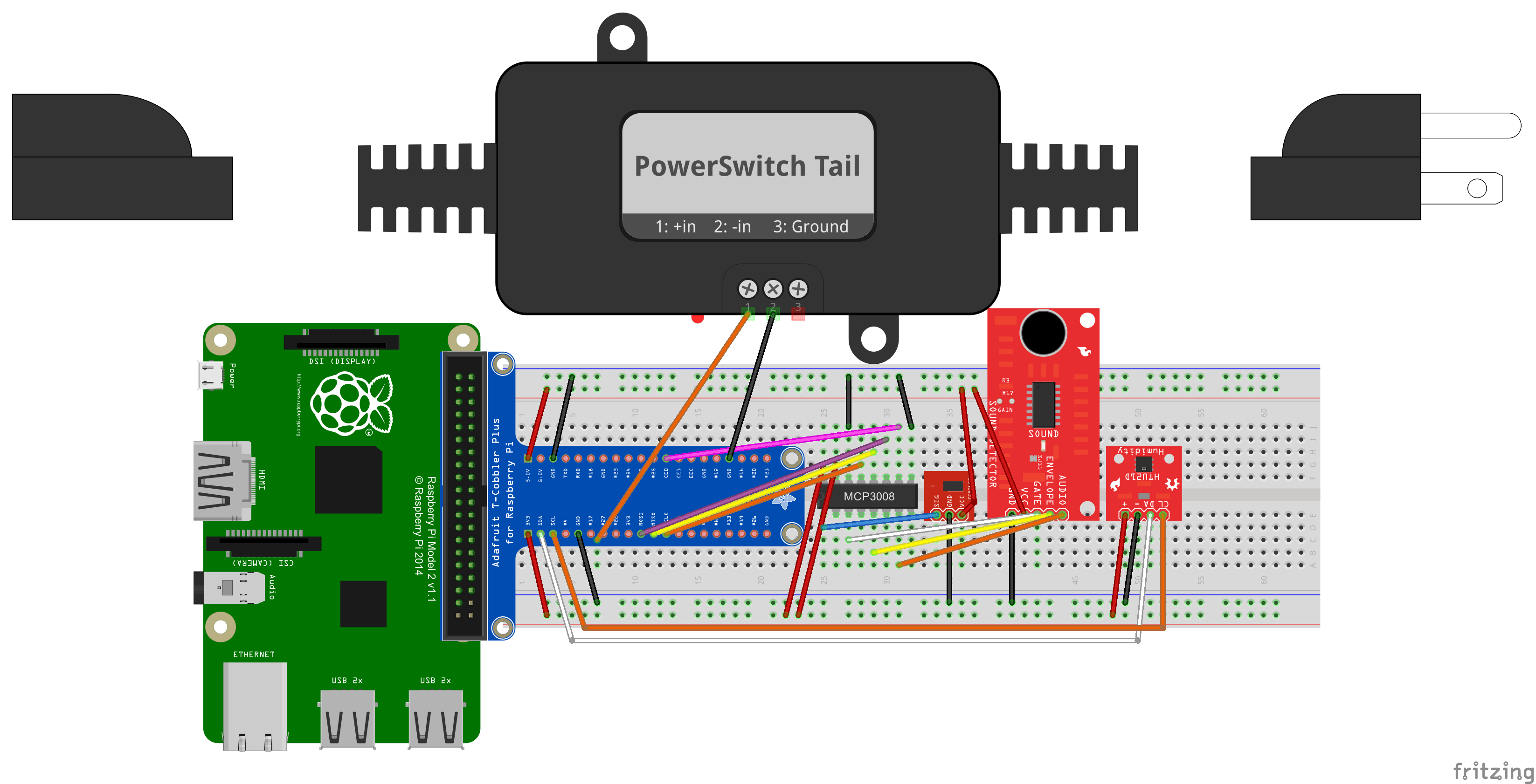
We are going to connect the temp/humidity board to the cobbler first, since it's digital and the easiest. You can see the Fritzing diagram below, or just connect as follows:
+ --> 3v3- --> GNDCL --> SCLDA --> SDA
Next, we need to connect the analog boards. To do this, I'm using a MCP3008, which is an 8-Channel 10-Bit ADC With SPI Interface.
The MCP3008 connects to the cobbler like so:
Vdd/Vref --> 3v3AGND --> GNDCLK --> SCLKDout --> MISODin --> MOSICS/SHDN --> CE0DGND --> GND
The rest is easy, we're going now connect the TEMT6000 to the MCP3008 by connecting the SIG to pin 1 (CH0). Connect GND to GND and VCC to the 5v power supply. Similarly, connect the Sound Detector's GND to GND and VCC to 5v. Now, connect the following:
AUDIO --> pin 3 (CH2)ENVELOPE --> pin 5 (CH4)GATE --> pin 7 (CH6)
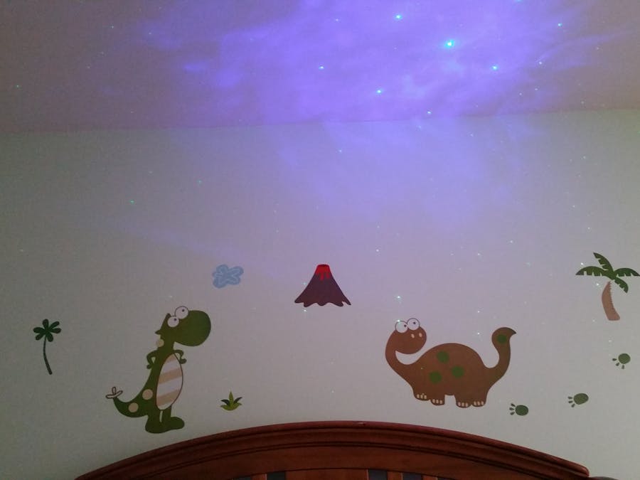
The next thing that I did was connect up a very cool device, called the PowerSwitch Tail II. This allows one to safely power on/off an AC device via a 3v3 signal. I plan to use this to power on a star-field projector when the audio reaches a particular level. Simply connect the #1 pin to #27 on the cobbler and the #2 pin to GND.
Programming the Raspberry Pi II
Now that we have everything hooked up and ready to go, it's time to program the Pi. In order to see what's going on, I chose to develop a simple Universal Windows application. There are a few parts that you need:
- A library to communicate with and read the HTU21D. I found a weather station hackster.io project that contains code to control the unit here.
- A page so that you can visually examine the values as they are being collected (I also put the collector code in here).
- A simple object class that we will serialize to send to Azure Event Hubs.
- An Event Hub helper class to actually send events to Azure.
The collector code took a while to figure out, but it seems to work, so I think I got it right. First, we need to initialize the SPI on the Pi:
//using SPI0 on the Piode>var spiSettings = new SpiConnectionSettings(0);//for spi bus index 0
spiSettings.ClockFrequency = 500000;
spiSettings.Mode = SpiMode.Mode0;
string spiQuery = SpiDevice.GetDeviceSelector("SPI0");
var deviceInfo = await DeviceInformation.FindAllAsync(spiQuery);
if (deviceInfo != null && deviceInfo.Count > 0)ode>{ode>_mcp3008 = await SpiDevice.FromIdAsync(deviceInfo[0].Id, spiSettings);ode>}
Besides the SPI initialization, the rest of the work is done in a timer click event. The light, audio, gate, and envelope code is all similar except for the channel address.
var transmitBuffer = new byte[3] { 1, 0x08, 0x00 };
var receiveBuffer = new byte[3];
_mcp3008.TransferFullDuplex(transmitBuffer, receiveBuffer);
var result = ((receiveBuffer[1] & 3) << 8) + receiveBuffer[2];
Azure
I utilize a few different Azure services for this project, but its primary usage is to aggregate timeseries events in 1 minute windows. This is done using Azure Stream Analytics. Events are pushed into an Event Hub every 10 seconds and are averaged over 1 minute windows:
SELECT
AVG(Light) as avglight,
AVG(Audio) as avgaudio,
AVG(Envelope) as avgenvelope,
AVG(Gate) as avggate,
AVG(Temp) as avgtemp,
AVG(Humidity) as avghumidity
INTO
output
FROM
input TIMESTAMP BY SensorTime
GROUP BY
Type, TUMBLINGWINDOW(Minute, 1)
The output gets sent into an Azure Service Bus Queue, which gets picked up by a simple Azure worker role.
var bodyJson = receivedMessage.GetBody<String>();
var reading = JsonConvert.DeserializeObject<AvgReading>(bodyJson);
NewRelic.Api.Agent.NewRelic.RecordMetric("Custom/AvgLight", reading.AvgLight);
The results get pushed into my New Relic account, where I produce a dashboard like this:
Next Steps
Due to the birth of my son, I was unable to accomplish everything that I set out to do. The next things that are to be completed are:
- Incorporate a load sensor to determine if he leaves the crib, stops breathing, etc.
- Use the aggregated data to determine when to turn on the star-field. Currently, it turns on when the audio reaches a certain level.
- Incorporate video. Currently, Windows IoT does not support the Raspberry Pi camera. When this is supported, I will set up a video stream so we can monitor baby Braden.


_3u05Tpwasz.png?auto=compress%2Cformat&w=40&h=40&fit=fillmax&bg=fff&dpr=2)
Comments