Following on from the GTEM ATM90E26 project, interest and feedback has been encouraging. The GTEM board design works very well and has received positive responses, however, with multiple inverters, the next challenge was to increase the number of inputs.
An enhanced board project, called IPEM, has been designed, based on an ESP32 integrated with an ATM90E32 (or ATM90E36), for direct 3 Phase, 3 x Single Phases or 1 x Split Phase (for USA), energy monitor. enhanced high-performance energy metering devices. These are complete current and voltages for each of the phases - fully user configurable.
With increased current sensor and AC voltage inputs, together with high dynamic range, the new IPEM board makes a good addition to the power energy monitoring projects.
Inline with my other MCU projects, I prefer the 'complete' board approach, where the ESP32 WROOM is included on the board, together with an EEPROM, for parameters and logging, plus a CH340 USB-UART, so providing 'Wemos D1 Mini' flashing, logging and debugging compatibility.
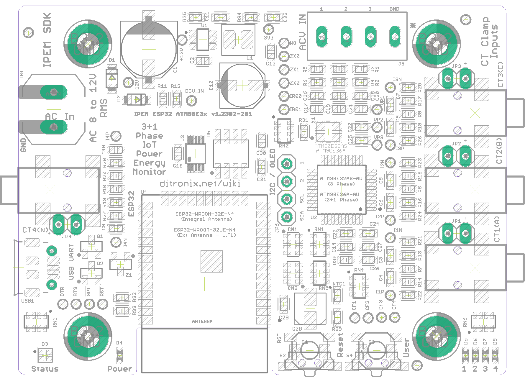
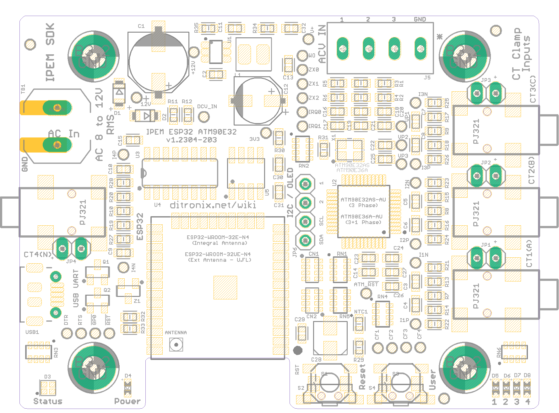
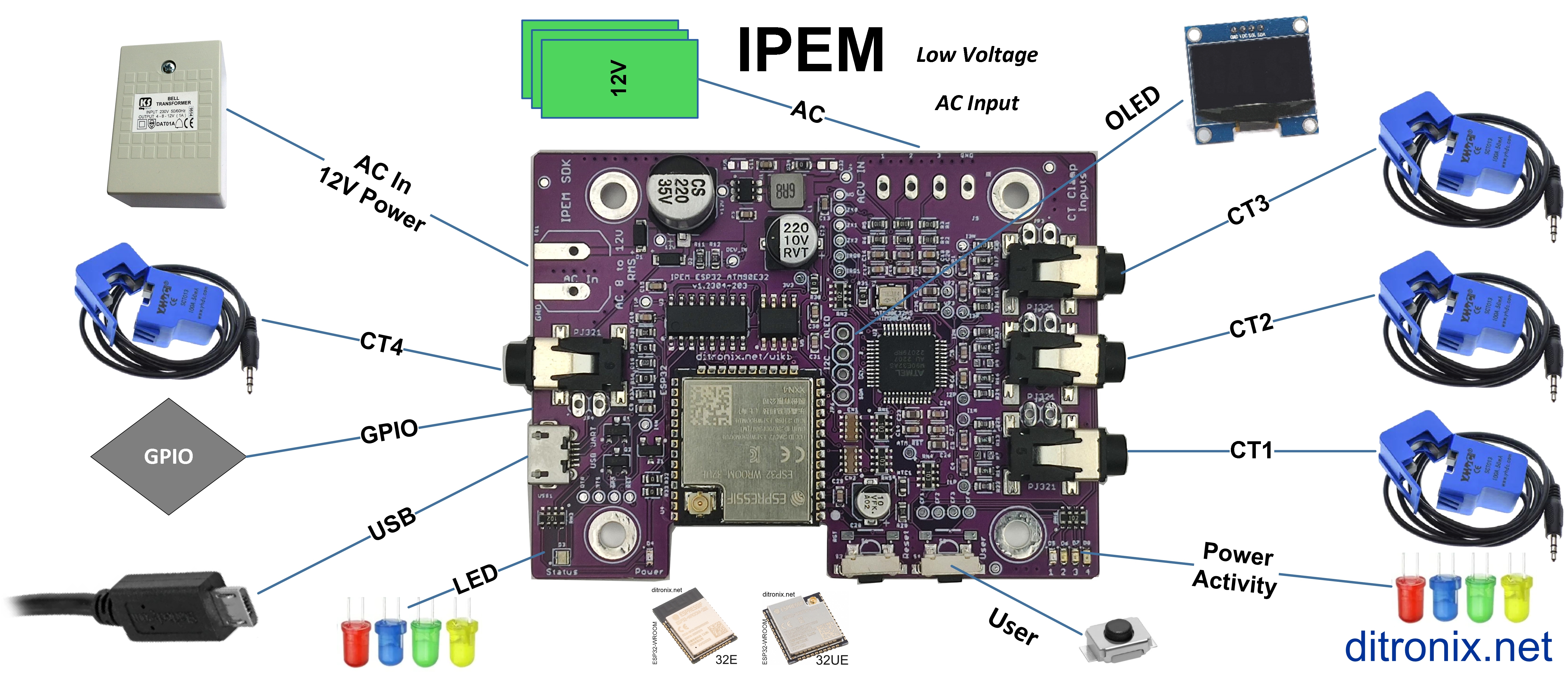
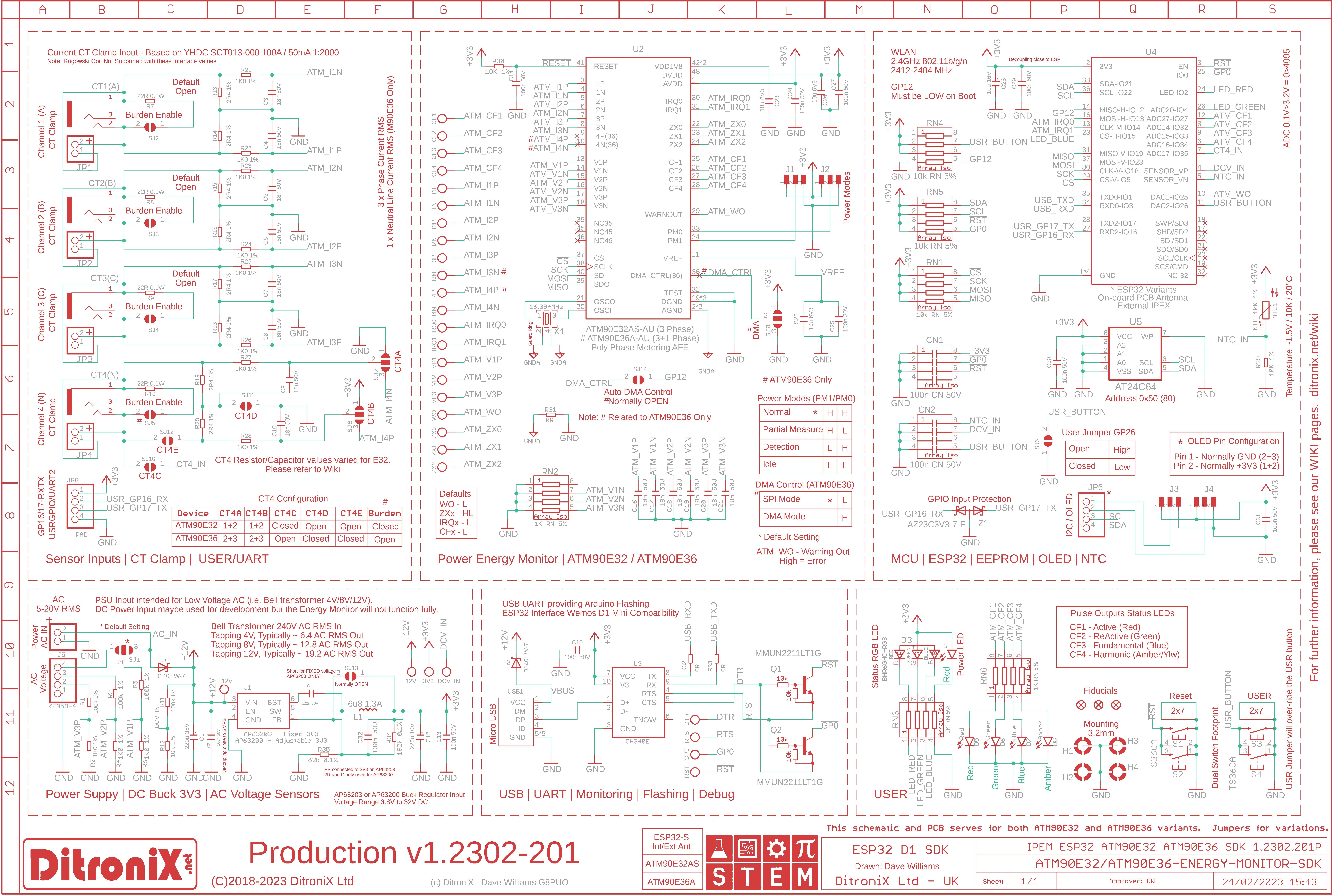
Board Overview
Web Push OTA
- The board is available to purchase from the website.
- Updated Firmware Installation Instructions
Example real-time output to ThingSpeak https://thingspeak.com/channels/2179490
Project History
Safety, Safety and more Safety!
An important criteria of the Energy Monitor was the ability to safely and indirectly connect to mains, without working on high voltages.
For this reason, the board contains low voltage AC sampling and a DC power supply, both derived from a singe low voltage AC input.
The AC input should be safely derived from a SELV (Safety Extra Low Voltage), 12V transformer. This type of power supply, much like Bell transformers, provides total isolation from the mains as it features a lack of a return path, through earth.
The separate commonly used current clamp simply snaps over a single meter tail cable, so is safety isolated too.
Note: Most wall chargers are either DC output (which is no good) or PELV. To learn more about the differences of SELV and PELV, this video provides a good insight.
Logging and Parameters
Storing parameters ,settings and even local logs is always useful. All our boards include an AT24C64 (EEPROM 64Kb - [8K x 8] Memory IC ).
This is easily accessed via I2C and Arduino EEPROM libraries. The Non-Volatile memory allows for data to be retained, even when power is off. Examples being Wi-fi settings, calibration data etc.
Flashing, Programming and Debug Logging
To make it easier to connect using just a Micro USB cable, the IPEM board includes a CH340 USB-to-serial UART. This IC is commonly used on boards like the Arduino D1 mini, requires no drivers and makes programming and debugging from the Arduino IDE and Visual Studio Code / Platform IO easy.
Update 12th February 2023. The BETA version of the board, populated and ready for testing.
Update 26th February 2023
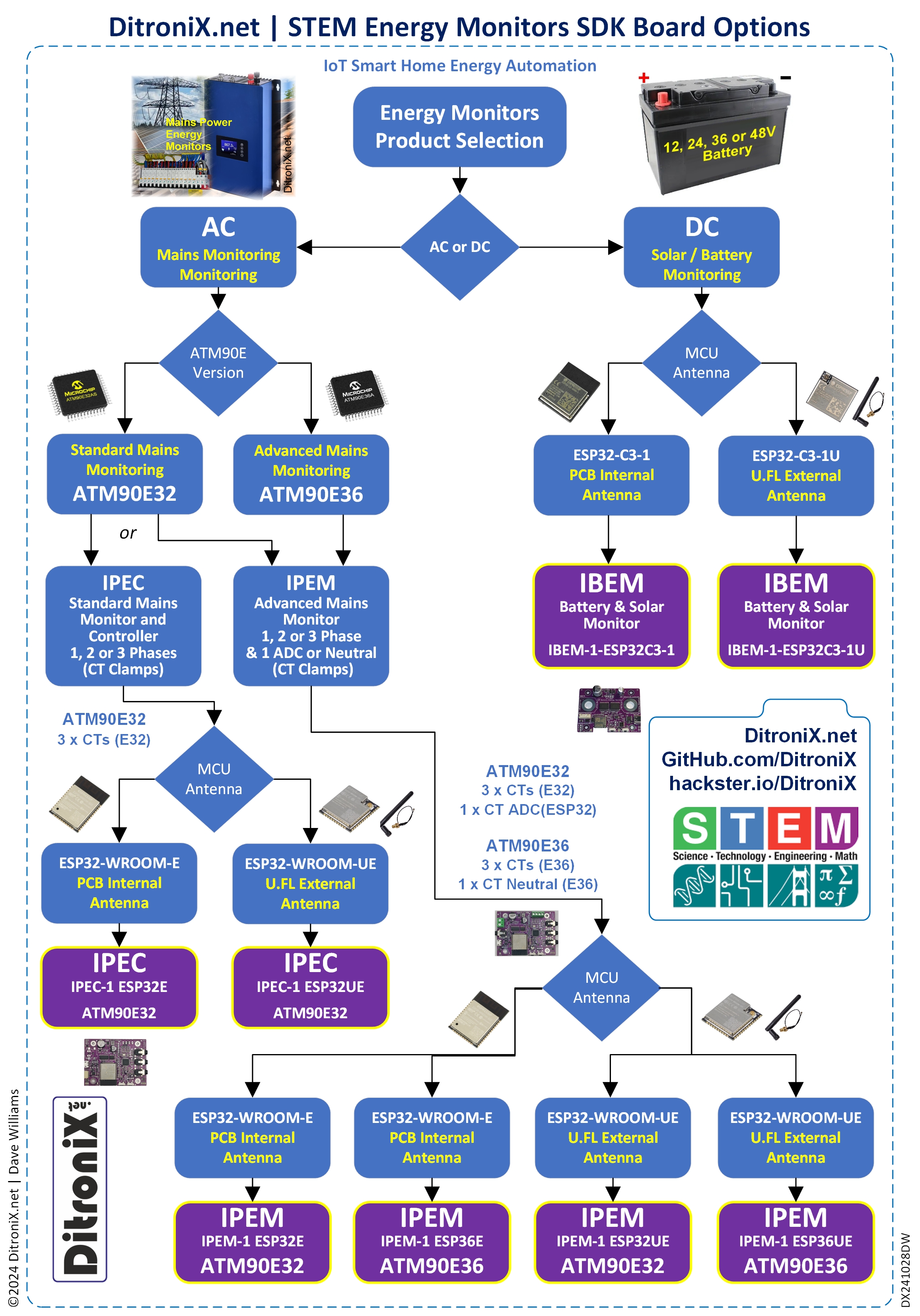
Two versions of the ESP32 will be available. Espressif (ESP32-WROOM-32E-N4 Internal PCB antenna and ESP32-WROOM-32UE-N4), external Antenna via the IPEX U.FL)..
The board has been finalised for production, further detail on my GitHub Wiki.
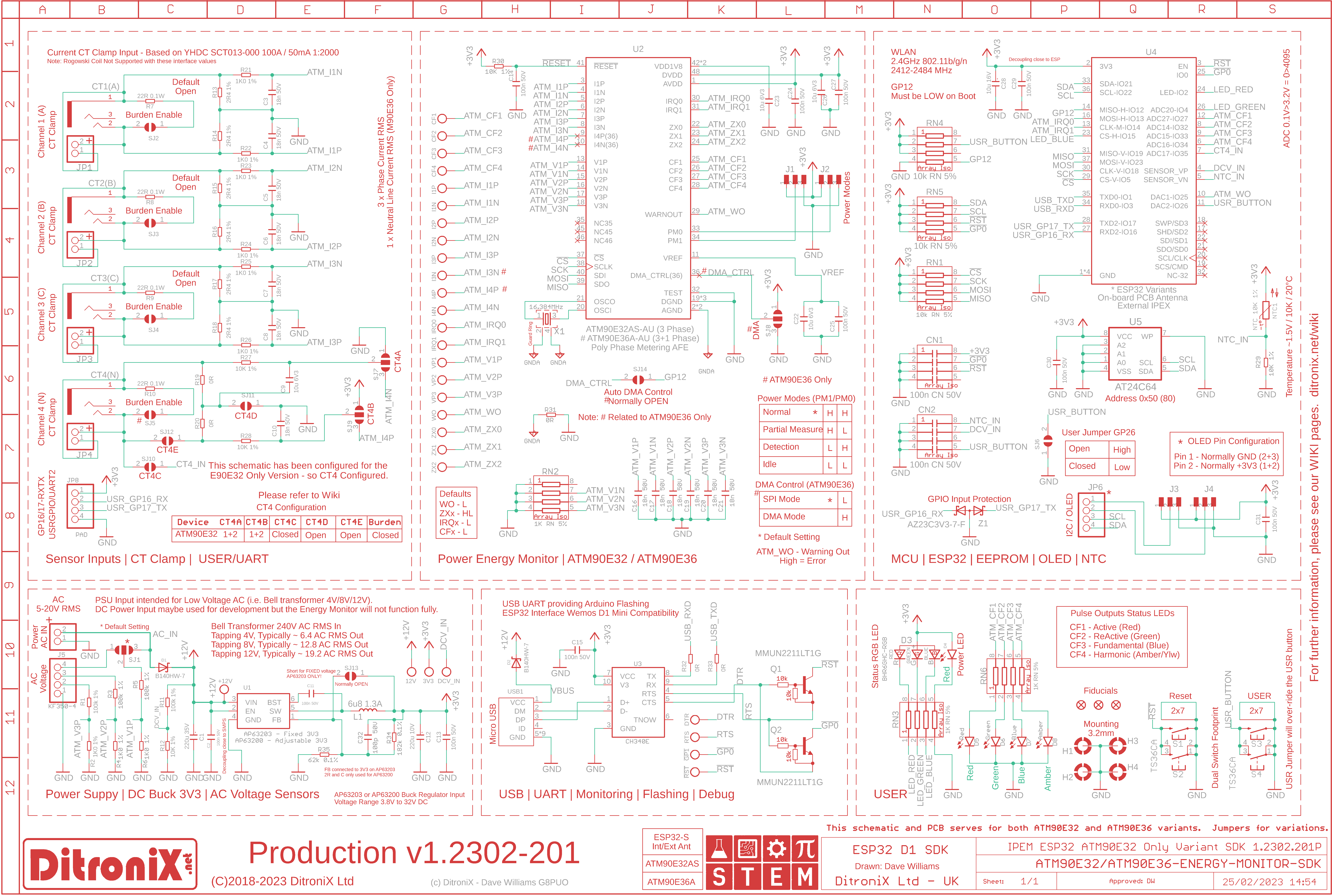
Further improvements to the design includes the ability to use the forth CT input on the ATM90E32 version. This has been achieved by allowing the port to be mapped via solder jumpers, to the ESP32 ADC.
Specification
Based on valued feedback, four versions of this project are planned, using a single board layout which has been designed to be a flexible dual purpose.
Update 4th March 2023
The schematic has been updated to 1.2303-201, to allow the option for the CT4 input on both ATM90E32 and ATM90E36 variants to optionally use the ESP32 ADC. This providing 4 single phase, or 3 phase + 1 single phase, monitoring from a single board.
Awaiting delivery of the first batch of production boards. The below 3D example is of the new board, rendered using Fusion360. Also showing the added 4 pin screw header to make it easier for the AC voltage input. These headers will be included with the board but not soldered.
Software examples
Some firmware to test the board has been uploaded, more to follow.
The main test and bring up firmware for both ATM90E32 and ATM90E36 variants has been merged into a single build. I did this to make it easier to maintain and update. Currently being tested, prior to upload to GitHub.
Update 23rd March 2023
The first release of test code has been uploaded. This has proved to be quite a large release, as it combines both ATM90E32 and ATM90E36, plus optional CT4 / CTN input and options. A small number of 'software switches' are used to configure as needed. Domoticz integration has also been included for most of the available registers and values. It is easy to configure and enable as needed.
With two small tweaks to the board, all is looking really good and working well.
Minor changes to the board revolves around the USB UART. A CH340C was included on the beta board and all the preliminary tests which gave Wemos D1 Mini compatibility and works well. However, when it came to first test production, only a CH340E was available, so the part was swapped last minute, not realising the DTR did not actually function as demonstrated via TNOW. So, now the CH340C is in stock, the board now only uses this part.
One other minor tweak was to allow the User Button to be configured on GP0 using a solder pad.
Expect the 2nd Production shipment (1.2303.202P) at any time, which will fulfil current orders. Many thanks to all, whom have showed interest and supported the design.
Update 21st May 2023
With the production IPEM boards in stock and interest gaining momentum, with really positive feedback, I am pleased to share the latest IPEM development code.
The latest updates include a range of improvements, Web Server, Push OTA, OLED Support, Increased Serial Monitor Information and a couple Buglet fixes.
Although the development code was originally intended for board bring-up and testing, with the latest features, it is now much more extensive and opens up to many real-time Home Automation and Industrial Monitoring applications. Integrated Domoticz publishing has also been extended, with more values.
* IPEM_1_Test_Code_ATM90E32_ATM90E36, is now at release 230520.
OLED displays WiFi Information and Mains Voltage, Rotating CT 1, 2 and 3 Power, with Import/Export. Whilst this example display below is an 0.6", a larger I2C display can easily be added.
Example Code Serial Monitor Output can be seen here
Update 25th May 2023
The main development firmware, now includes MQTT as well as integrated Domoticz publishing. Work is already underway to also include others, such as ThingSpeak.
List of Domoticz and MQTT Variables which you can easily publish from within the development code.
What does this mean? Well, the firmware application will not only test the board and allow development of ideas, it includes integrated publishing to Home Automation, with WiFi connections and Push OTA - to simplify updating once deployed.
Update 16th June 2023
The IPEM development code has been updated.
- Tweaks for Improvements
- Added PWM Output which will monitor a designated CT Power variable and output PWM (default ActivePowerExportCT1). Output Updated on Each DisplayRegisters Loop (Only if Value Changed)
- Added DAC Output which will monitor a designated CT Power variable and output a DAC Voltage 0-3.3 (default ActivePowerExportCT1). Output Updated on Each DisplayRegisters Loop (Only if Value Changed)
- Webserver Listener for first round of Soft Web Controlled Switches. Can be driven from Browser URL, or Domoticz for example
- PWM Switches added: /pwm-local, /pwm-remote, /pwm-on, /pwm-off, /pwm-test
- DAC Switches added: /dac-local, /dac-remote, /dac-on, /dac-off, /dac-test
- Separate switches dac-remote and pwm-remote, allow you to remotely send a fixed value to pwm / dac output. Ideal for scenes etc. Remote turns off or over-rides CT for pwm/dac.
- Added more variables for Domoticz, ThingsSpeak and MQTT Publishing
- Bug Fix in bool ATM90E3x::calibrationError. systemstatus0 & 0x1000. Thanks AndyM
- Bug Fix OLED in Display Loop ActivePowerExportCT3. Thanks AndyM
AC Input
The board has three AC Inputs. However, it is important to connect all three in parallel for some readings. Information can be found in the Wiki.
In summary, you need to do this.
DAC Modification.
Should you wish to use the DAC output, you will need to break the connection from DAC1 to WO. Then connect to the DAC1 on the ESP32. On the next IPEM revision, I will include a header for this,.
In summary, you need to do this. Note: Pending board revision, the track position may alter.
Updates code can be found on our GitHub.
The full specification list is available here.
Further details maybe also be found on our GitHub
Supporting STEM
Life is one long exciting learning curve, help others by setting the seed to knowledge.




Comments
Please log in or sign up to comment.