This IoT project will help reduce carbon dioxide emissions into the atmosphere in different parts of the world since carbon emission is the number one contributor to air pollution.
The problem this project solvesThis project collects carbon dioxide and noise sensor data and sends the data to Amazon Web Services (AWS) where it is securely stored in a real-time streaming database and analyzed. It differs from existing solutions in using a siren to indicate the unacceptable high carbon dioxide and noise levels. It is an important device that will the United Nations reach its 17 Millennium Goals.
The main features of this solutionThis solution uses a carbon dioxide sensor to collect carbon dioxide data and a microphone to collect noise levels in an area where it is installed. If the levels of carbon dioxide emission and noise exceed the maximum levels allowed in that area, it will trigger the alarm and set red flags on the sensor data. This solution includes the following main features: 1. PSoC6 2. Carbon Dioxide Sensor 3. Microphone. This uses the Wi-Fi PSoC6 Development Board to connect to AWS IoT Core service where I will store carbon dioxide sensor data and noise data from the microphone. This smart IoT project will also be used to establish the relationship between carbon dioxide and noise.
How to build this project
Step 1: Hardware Components
This Grove SHT40 digital sensor is based on Sensirion's industry-proven humidity and temperature sensors. It can provide constant temperature and humidity accuracy over an extensive measurement range, making it the best price/performance ratio available. With the Grove platform, you are ready to plug and play the SHT4x sensor on any microcontroller (Arduino) or microprocessor (Raspberry Pi).
The Grove-SHT40 digital 4th generation sensor comprises an entirely new and optimized CMOSens® chip, offering lower power consumption, which makes it highly suitable for low-power and battery-supported applications. It has an operating temperature range of -40°C to +125°C, an excellent 1.8% typical relative humidity accuracy from 25 to 75%, and a 0.2 °C typical accuracy from 0 to 75 °C.
The fully calibrated Grove-SHT40 sensor offers linearized digital output and NIST traceability. Our standard Grove four-pin I2C interface makes it easy to read or communicate with integrated circuits.
Due to the high accuracy of the SHT40 sensor and the compatibility of the Grove system, Grove-SHT40 is perfect for high-end industrial applications, projects for hobbyists, learning projects for beginners, etc.
Figure 4: Grove - VOC Gas Sensor (SGP40), Volatile Organic Compound detection, I2C
The Grove - VOC Gas Sensor (SGP40) is an innovative environmental sensing module developed for a wide array of Volatile Organic Compound (VOC) detection applications. Based on the advanced Sensirion SGP40 sensor, it excels in transforming raw sensor signals into standardized digital signals for seamless integration into existing systems.
One of the key advantages of the Grove - VOC Gas Sensor (SGP40) is its communication protocol. The sensor module uses the I2C interface, a widely adopted protocol known for its simplicity and efficiency. This makes the data transfer process between the sensor and your main controller extremely smooth, enabling quick reaction times for applications where immediate actions based on VOC levels are crucial.
Infineon’s XENSIVTM S2GO_Hall_TLE4964-3M boards offer a unique customer and evaluation experience – the boards are equipped with one TLE4964-3M magnetic hall sensor and come with a ready-to-use Arduino library. Customers can now develop their own system solutions by combining Shield2Go boards together with Infineon My IoT adapters. My IoT adapters are gateways to external hardware solutions like Arduino and Raspberry PI, which are popular IoT evaluation platforms. All this enables the fastest evaluation and development of IoT systems on the market!
Figure 6: XENSIV™ - Shield2Go equipped with TLI493D-W2BW-A0 - 3D magnetic sensor
Infineon’s new XENSIVTM S2GO_3D_TLI493D-W2BW-A0 boards offer a unique customer and evaluation experience – the boards are equipped with one TLI493D-W2BW-A0 magnetic sensor and come with a ready-to-use-Arduino-library. Customers can now develop their own system solutions by combining Shield2Go boards together with Infineon My IoT adapters. My IoT adapters are gateways to external hardware solutions like Arduino and Raspberry PI, which are popular IoT evaluation platforms. All this enables the fastest evaluation and development of IoT systems on the market! It can be used together with the XMC2go platform (plugged on top as depicted below: the sensor is placed above the USB connector). The hardware can be also connected remotely to any 3.3V compatible development kit. Attention: Do not connect the shield directly to Arduino UNO platforms which are operating at 5V!
There are many people whose active and passive buzzer concept is not very clear, here is a brief introduction that we want to be helpful for future use.
Note that the “source” does not mean power. But rather refers to the shock source.
The passive buzzer is characterized by:
A passive internal source without shocks, so if the DC signal can not make it with a tweet. Must 2K ~ 5K square wave to drive it 2 sound frequency controllable, you can make a “more than a meter hair Suola Xi” effect.
3 In some special cases, you can reuse a control and LED mouth
The active buzzer is characterized by:
An active internal buzzer with a shock source, so long as a power will be called
2 program easy to control, SCM can allow high and low sounds, while passive buzzer can not.
One module description
A module using a 9012 transistor drive
2 Operating voltage 3.3V-5V
6 with fixed bolt hole for easy installation
7 small plates PCB size: 3.3cm * 1.3cm
Two-module interface specification (3-wire)
1 VCC external 3.3V-5V voltage (5v microcontroller and can be directly connected to 3.3v MCU)
This is a lightweight, high-energy density Lithium Ion polymer battery. It outputs a nominal 3.7v at 3300mAh and comes terminated with a standard 2-pin JST connector- 2mm spacing between pins.
This is a buck-boost converter board that keeps a pre-set voltage even if the voltage is below (step-up) or above (step-down) the pre-set value. It works especially significant where the power source fluctuates a lot e.g. solar panels
This is called a Cuk converter a type of DC/DC converter that has an output voltage magnitude that is either greater than or less than the input voltage magnitude. It is essentially a boost converter followed by a buck converter with a capacitor to couple the energy.
Please note that the trim pot that is used to adjust the output of the module needs to be turned quite a few times before you can see a change in the output.
Contact Resistance 30mΩ
maxInsulator Resistance 1000MΩ
min. @DC 500VCurrent Rating1
AVoltage Rating 30V
ACDielectric Strength AC 500V for 1 minute
contact Material
Phosphor BronzeHousing
PBT & 30% Glass Fiber (UL94V-0)
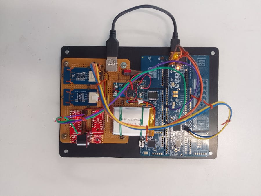
Figure 11: experimental stripped prototyping board.
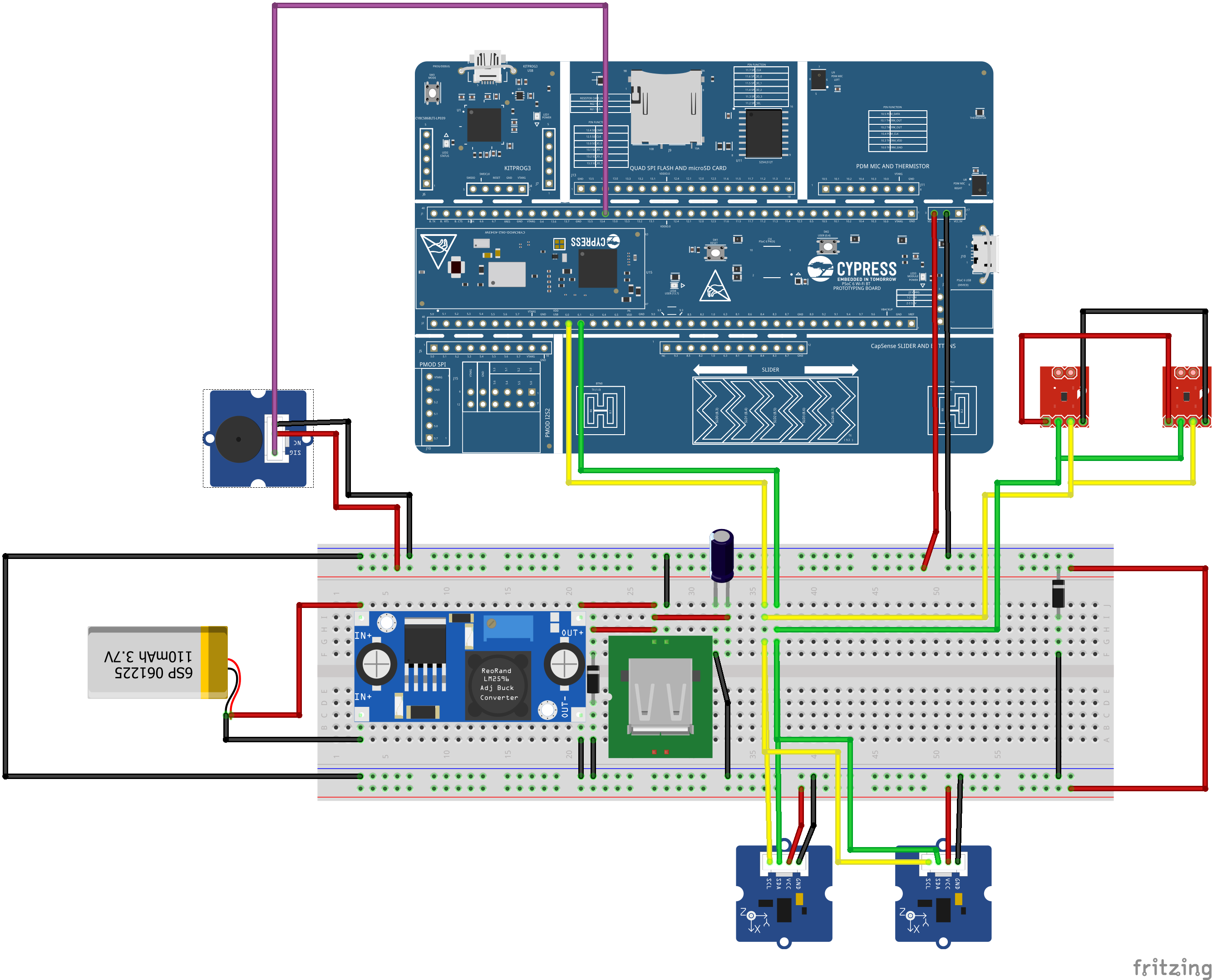
Figure 11 shows all the sensors connected to the experimental stripped prototyping board.
This is a black rigid plastic stander on which the whole project is mounted.
==============================================================================================================================================
Step 2: Software Components
Install within virtual environment
Install globally
1. Create a new virtual environment:
2. Activate the virtual environment:
Once activated your shell will be prefixed with
(.venv)
. The virtual environment can be deactivated at any time by running
deactivate
Note: Remember to activate the virtual environment every time you start working.
3. Install west:
4. Get the Zephyr source code:
cd %HOMEPATH%
python -m venv zephyrproject\.venv
:: cmd.exe
zephyrproject\.venv\Scripts\activate.bat
:: PowerShell
zephyrproject\.venv\Scripts\Activate.ps1
pip install west
west init zephyrproject
cd zephyrproject
west update
5. Export a Zephyr CMake package
. This allows CMake to automatically load boilerplate code required for building Zephyr applications.
6. Zephyr’s scripts\requirements.txt
file declares additional Python dependencies. Install them with
pip west zephyr-export
pip install -r %HOMEPATH%\zephyrproject\zephyr\scripts\requirements.txt
1. Open a cmd.exe
window by pressing the Windows key and typing “cmd.exe”.
2. Download the Zephyr SDK bundle
3. Extract the Zephyr SDK bundle archive:
cd %HOMEPATH%
7z x zephyr-sdk-0.16.3_windows-x86_64.7z
cd %HOMEPATH% \zephyrproject\zephyrwest
build -p always -b cy8cproto_062_4343w samples\basic\smart_pollution_indicator
west flash --openocd path/to/infineon/openocd/bin/openocd.exe
Open the Visual Studio Code
Go to File->Folder and open a folder containing the smart_pollution_indicator Zephyr Project
Click Select root directory and navigate to your application build directory where the.project file is generated.
Open the main src code
smart_pollution_indicator main src
smart_pollution_indicator main src
Open the dashboard 3.1.0
4 Set up a debugger in Eclipse IDE for ModusToolbox™
4.1 Generate the project description file
1. In the command prompt, navigate to the Zephyr application directory:
cd "C:\zephyrproject\zephyr_example_filesystem_littlefs"
2. Build the application by executing the following command:
west build -b cy8cproto_062_4343w -- -G"Eclipse CDT4 - Ninja"
Note: A different CMake generator is specified by the -G"Eclipse CDT4 - Ninja" argument. This
will generate an Eclipse project description file (.project) in addition to the usual Ninja build files. generated. Select your project from the list of projects and click
3. In Eclipse IDE for ModusToolbox™ 2.4, choose a new workspace.
4. Select File > Import and then select General > Existing Projects into Workspace to import your generated project.
5. Click Select root directory and navigate to your application build directory where the.project file is
Create a debugger configuration in Eclipse IDE for ModusToolbox™
1. Select Run > Debug Configurations.
2. Select GDB OpenOCD Debugging, click New
3. Configure the following options on the Main tab:
• Name: smart_pollution_indicator
• Project: Browse -> smart_pollution_indicator@build
• C/C++ Application: <your Zephyr project repo> -> zephyr/zephyr.elf
4. Navigate to the Debugger tab, and make the following changes:
a) OpenOCD Setup:
− Executable path: {$openocd_path}/{$openocd_executable}
− Config options:
- s "${openocd_path}/../scripts"
- c "source [find interface/kitprog3.cfg]"
- c "transport select swd"
- c "puts stderr {Started by GNU MCU Eclipse}"
- c "source [find target/psoc6_2m.cfg]"
- c "psoc6.cpu.cm4 configure -rtos auto -rtos-wipe-on-reset-halt 1"
- c "gdb_port 3332"
- c "psoc6 sflash_restrictions 1"
- c "init; reset init"
b) GDB Client Setup:
− Executable name: ${cy_tools_path:CY_TOOL_arm-none-eabi-gdb_EXE}
5. Navigate to the Startup tab, and make the following changes:
• Uncheck Initial Reset under Initialization Commands.
• Do the following in the Run/Restart Commands section:
a) Change the Type to run.
b) Add the following commands inside the textbox:
mon psoc6 reset_halt sysresetreq
flushregs
mon gdb_sync
stepi
6. Navigate to the SVD Path tab, and make the following changes:
• Set File path to: C:\zephyrproject\modules\hal\infineon\mtb-pdlcat1\
devices\COMPONENT_CAT1A\svd\psoc6_02.svd
7. Click Apply and then click Debug.
Figure 35: Flash the smart_pollution_indicator
For more information on debugging, see the following:
• ModusToolbox™ user guide
• Zephyr documentation: Set up the debugging environment for Eclipse


_SPmZ63wPgQ.png?auto=compress%2Cformat&w=40&h=40&fit=fillmax&bg=fff&dpr=2)
Comments
Please log in or sign up to comment.