- ABSTRACTThe aim of this project is to design and implement an air quality monitoring system. This project activates actuators to be able to maintain better air quality around us. This project can be used in our houses, warehouses, and greenhouses. It has a line following the robot on which there is the sensor that measures temperature, humidity, light intensity, and the presence of gas around. Whenever the parameters go beyond the set threshold, it activates an output to try to cancel out the change which is caused. Moreover, the data read is stored in a NodeMCU ESP8266, an IOT module, which is then transferred to the Blynk cloud app. All the data collected is accessible through the Blynk on a smartphone. The user can also see which actuator is in use.
If you want this project code and dot board PCB "Call Me".
Contact number  : "+91 8217878840"
Whatsapp number : "+91 8217878840"
Gmail id : "embeddedtechet@gmail.com"- INTRODUCTIONThe term “air quality” means the state of the air around us. Good air quality refers to clean, clear, unpolluted air. Clean air is essential to maintaining the delicate balance of life on this planet — not just for humans, but wildlife, vegetation, water, and soil. Poor air quality is a result of several factors, including emissions from various sources, both natural and “human-caused” (Future, 2022). According to Converse Energy Future, the condition of the air which is surrounding us is defined as air quality. When we speak of good air quality, it is understood that the air is fresh, and pure and does not contain any contaminants such as smog, smoke, dust amid other impurities in the air. Air quality is defined by estimating several indicators. Proper air quality is vital for animals, plants, humans, and natural resources to preserve the delicate stability of life on earth. As a consequence, when pollution levels in the air reach toxic levels, animals, plants, human health, and natural resources are risked. Poor air quality can bring an adverse impact on human well-being as well as the environment. There are many ways in which air quality can worsen. The causes can be either man-made or natural sources. For example, industries, cars, and coal-fired power plants are sources of man-made pollution and volcanic eruptions, and windstorm dust is an example of a natural source.
Figure 1 shows the components connected to the robot part. The line-following robot also avoids obstacles with the help of the ultrasonic sensor and servo motor. With an obstacle present, the servo motor turns 90° left and then 90° left to check whether there the path is clear to continue its path.
Input RF transmitter partFigure 4shows the steps that will take place when it starts. All data captured will be stored in the ESP8266 to be transferred to the mobile application.
Output conditionsTemperature conditionThe flowchart above describes the conditions that need to be met to have the output part on or off. The system is designed to use a cooling system to maintain the required condition. As we are based in Mauritius (a tropical island), we would rarely be in need of a heating system taking into consideration the data collected in Appendix 1.
Humidity conditionThis system will be met when the humidity is above 70% whereby a humidity fan will be on and otherwise. When the humidity is too high, the humidity fan will be on. Taking into consideration Table 15 from Appendix 1 shows that the mean humidity in Mauritius is always above 70% and hence the condition whereby humidity is low will be quite useful here.
Light intensity conditionThis part of the system is based on the availability of light intensity. When it is too dark in the space when the robot and the sensors, an LED will be automatically on.
MQ-2 Sensor conditionThe MQ-2 sensor detects any gas or smoke which is near the system and a buzzer is activated to signal the user.
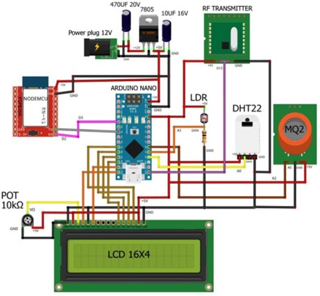
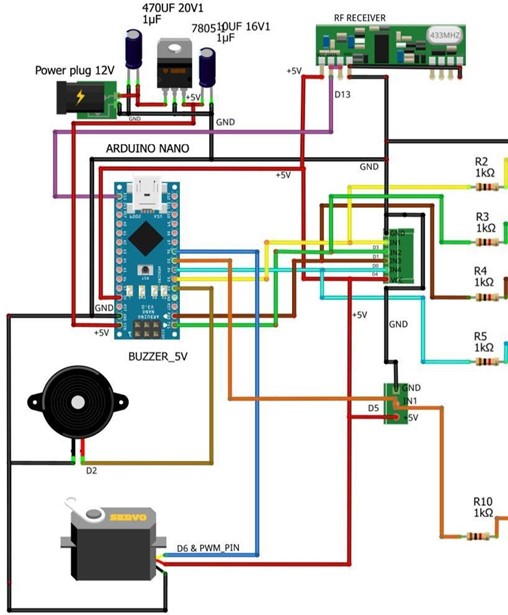
Working principle- There are 2 PCB boards with both having a nano Arduino as controller. One board comprises all the sensors which include the DHT22 sensor, LDR, and MQ-2 sensor. All the parameters appear on a 20x4 LCD. The LCD shows the temperature and humidity and whether any outputs are activated. The second board comprises all the outputs of the sensor. The 2 boards communicate with each other with an RF 433 MHz module. The transmitter sends a signal to the receiver to actuate any output.
- The board with all of the sensors will be placed on a line following their robot circulating around the dedicated place.
- The line of the following robot has 2 IR sensors and 1 ultrasonic sensor. The IR sensor follows the black-taped line. An Arduino Uno with a motor shield is placed under the robot to control the 2-dc motor of the robot.
- The transmitter side contains all the sensors which will take readings for the surrounding air and an LCD display that shows the parameters of these sensors.
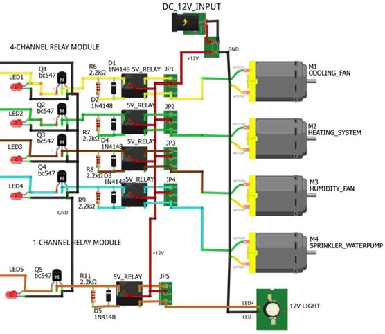
- Each sensor has its corresponding output. According to their condition, each output will be activated or deactivated.
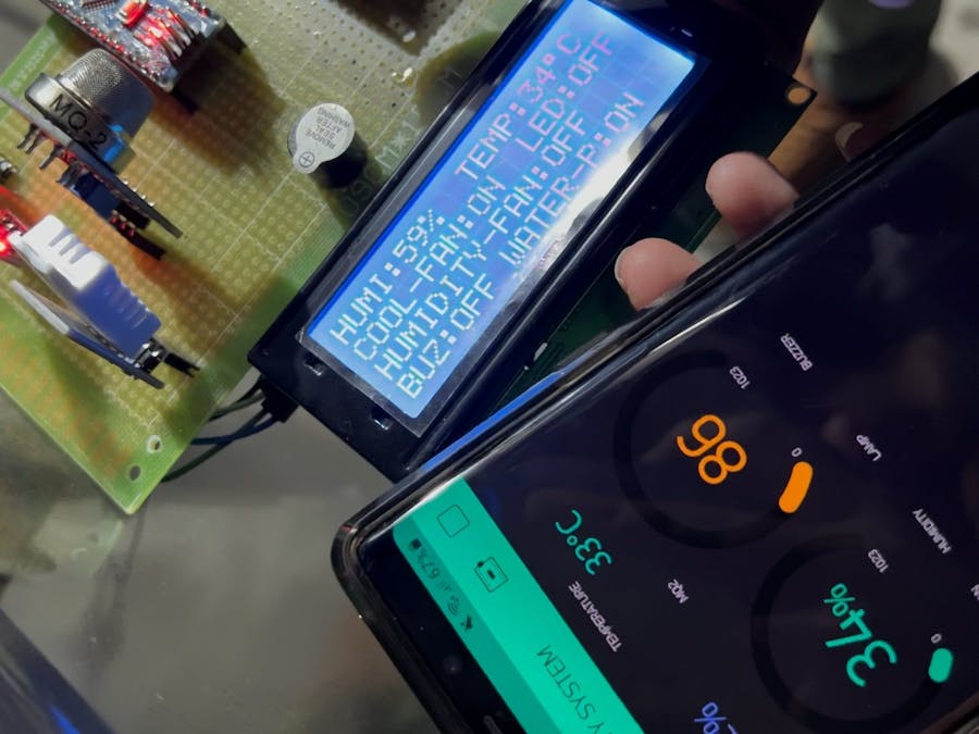
From the figure above, we can see the parameters of the input part and whether there is any output on or off.
Internet of ThingsThe IoT part of this project is used using ESP8266WIFI and Blynk application.
Each time the reading of the sensor is changed, it is updated on the ESP8266, then uploaded to the Blynk app. Figure 11 shows the air quality system with all the parameters showing and Figure 11 also shows that humidity and lamp are on.
Below, each condition will be tested and shown in figures from the Blynk App.
Testing of temperature conditionIn Figure 13, the DHT22 is heated up using a soldering iron. As the threshold temperature is reached, the cooling fan and water pump are activated as shown in Figure 14 from the Blynk App.
Testing of humidity conditionFrom Figure 14, it is shown that when the humidity is above the threshold mentioned in 2.2 Standards, the humidity fan is on.
Testing of light intensity conditionFrom Figure 14, when the LDR does not receive enough light, the readings turn to 1023, and the lamp is on.
Testing of MQ-2 SensorFrom Figure 15, a source of smoke is put near the sensor and we can see from Figure 16 that when the sensor detects the smoke, the buzzer is on.


_3u05Tpwasz.png?auto=compress%2Cformat&w=40&h=40&fit=fillmax&bg=fff&dpr=2)


Comments
Please log in or sign up to comment.