/* Radio Receiver
* Adeept UNO with Motor Shield V2
* Radio module: nRF24L01 + PA + LNA with antenna built in -USE 3V !!!! built in, 5V is fine ONLY with shield or adaptor, or bypass capacitor, see specs
* L298N - 7.4 V input - two 46850 batteries , use whatever you like .
* Can be done with any pair of UNOs - Written by Gallax
*
* L298N is grounded to Uno.
*
* Servo pin 2 or P4 on Adeept shield
* CE 9 CSN 10 for Adeept shield
*
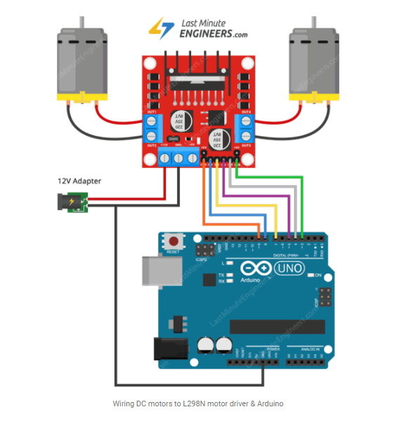
* ////////////L298N CONNECTIONS ON ADEEPT SHIELD OR UNO ////////////////
* IN1 IN2 IN3 IN4 SPD1 SPD2
* 8 4 7 5 9 3
*
* I didnt use RF24 Adaptor, shield has one built in. So this is universal for Unos.
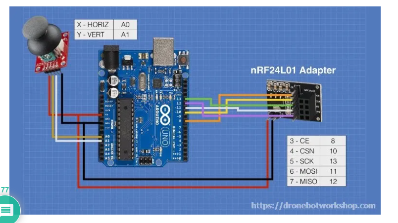
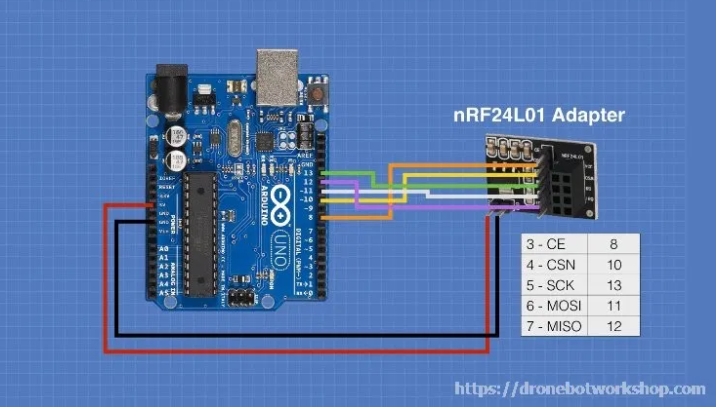
* * ////////////////////// RF24 Adaptor or use this pinout :) /
* __________________________________
* || 3V || 10 || 11 || NC || NC - not connected.
* || VCC-||-CSN-||- MOSI-||- IRQ ||
* ||_____||_____||_______||_______||
* || GND-||-CE -||- SCK -||- MISO ||
* || GND || 9 || 13 || 12 ||
* ||_____||_____||_______||_______||
*
* ///////////////////////////Servo connection //////////////////////////
*
* Servo is connected to 5V, GND, pin is 2 (search for servo.attach for reference)
* Adeept shield requires pin 2 = P4 - yes this was quite a job.
*
*/
#include <SPI.h>
#include <nRF24L01.h> // include RF24 libraries
#include <RF24.h> // This will need some tweaking. Excellent job.
#include <Servo.h> // Include Servo library
Servo servo; // creates servo object to control servo
// twelve servo objects can be created on most boards
RF24 radio(9, 10); // CE, CSN
const uint64_t pipe = 0xE8E8F0F0E1LL; // sets channel
// const byte address[6] = "00001"; // alternative
int data[8]; // create dataset array 8 bit
int enA = 9; // speed control A
int in1 = 8; // Motor A connections
int in2 = 7;
int enB = 3; // speed control B
int in3 = 5; // Motor B connections
int in4 = 4;
int xDir = 90; // initial direction for servo later
////////////////////////////////////////////////////////////////////////
void setup() {
Serial.begin(9600); // start serial monitor for debugging
radio.begin(); // starts the radio
radio.openReadingPipe(0, pipe); // sets this RF24 as receiver
radio.setPALevel(RF24_PA_MIN); // sets radio signal strength
radio.setDataRate(RF24_250KBPS); // sets datarate to 250 kbps
radio.startListening(); // starts listening for data
/// ///////////// Set all the motor control pins to outputs/////////////////
pinMode(enA, OUTPUT); // speed control motor A on L298N
pinMode(enB, OUTPUT); // speed control motor B on L298N
pinMode(in1, OUTPUT); // motor A output - will become forward high
pinMode(in2, OUTPUT); // motor A output - will become forward low
pinMode(in3, OUTPUT); // motor B output - will become forward high
pinMode(in4, OUTPUT); // motor B output - will become forward low
servo.attach(2); //sets servo pin to 2 = P4 on Adeept Shield
}
//////////////////LISTEN, READ, MAPPING AND PRINTING DATA////////////////////
void loop() {
radio.startListening(); // receiver starts listening
if (radio.available()) { // if the radio has connection
radio.read(&data, sizeof(data)); // read all in the dataset, sizeof is for numeric purposes
int x = map(data[0], 0, 1024, 0, 180); // creates integer x, maps data[0], 0 is the first integer i used for the array, other than starting at 1
int y = map(data[1], 0, 1024, 0, 255); // now data is next in line at 1.
// maps data from 0 - 1024 --- converted by me to 0 - n where n = 180 or 255
Serial.print("x:"); // serial print text for reading
Serial.println(data[0]); // (note only one with ln)print data, if fails, check connections. (note only one with ln)
Serial.print("y:"); //prints text
Serial.print(data[1]); // prints the next piece of data
Serial.print("\t"); // i dunno, youll see why i didnt change this
/////////////////////IF DATA RECEIVED - SERVO CONTROLS//////////////////////
if ( data[0] == 0 ) { // if data 0 is equal to 0. servo turns left
xDir = 180; // see unit circle
servo.write(xDir); // TURN
delay(15); // small wait
}
if ( data[0] > 600 ) { // if data is greater than or equal to 600
xDir = 0; // dir is 0
servo.write(xDir); // TURN
delay(15); // rinse repeat
}
if (data[0] == 329 or data[0] == 328 ) { // more if data for x axis, (steering)
xDir = 90; // 90 is straight
servo.write(xDir); // no turn
delay(15); // small wait
}
/////////////////////IF DATA RECEIVED - MOTOR CONTROLS///////////////////////
if ( data[1] >= 650 ) {
analogWrite(enA, 255);
analogWrite(enB, 255);
// Set motors to maximum speed
// For PWM maximum possible values are 0 to 255
// Turn on motor A & B
digitalWrite(in1, HIGH);
digitalWrite(in2, LOW); // GO MOTORS!
digitalWrite(in3, HIGH);
digitalWrite(in4, LOW);
}
/********************************************************************/
else {
analogWrite(enA, 0);
analogWrite(enB, 0);
digitalWrite(in1, LOW); // STOP MOTORS
digitalWrite(in2, LOW);
digitalWrite(in3, LOW);
digitalWrite(in4, LOW);
}
/////////////////////////////////////////////////////////////////////
if ( data[1] <= 10 ) {
analogWrite(enA, 255);
analogWrite(enB, 255);
digitalWrite(in1, LOW); // BACKWARDS MOTORS
digitalWrite(in2, HIGH); // if failed Check your wires, motor faces up (red wire on top)
digitalWrite(in3, LOW);
digitalWrite(in4, HIGH);
}
/////////////////////////////////////////////////////////////////////
else { // waiting for connection, or NOT connected
Serial.println("Not connected"); // prints a line of text
delay(1000); // waits/repeats every second
} // delete this else statement if it becomes an eyesore
}
}
//////////////// END /////////////////


_3u05Tpwasz.png?auto=compress%2Cformat&w=40&h=40&fit=fillmax&bg=fff&dpr=2)
Comments
Please log in or sign up to comment.