Intro: In this Project I show you how to use a $1 Motion Sensor and a stickable LED Strip to make your room smarter and safer for you. When your feet drop down from you bed or you enter your room, lights under your bed will illuminate your floor area. The best part is there's no coding needed to get this to work! Here are the Steps you Need to make this happen or watch this YouTube Video:
Step 1: Using the PIR Motion SensorIn this project I am using 12VDC because that is what standard LED Strips run off of and this is within the operating Voltage of this PIR Unit (4.5V-20V).
Basically, all you need to worry about is the pins. VCC gets 12V, GND gets 0V or ground of the power supply and the Output Pin will output a 3.3VDC signal when sensing motion. This signal will be used with a MOSFET to turn the lights on and off.
Other than the pins, the Adjustment knobs are useful when determining how long the lights will stay on with a trigger and how sensitive you want the Sensor to be. Below you can see how to adjust these settings on the module itself.
This website has all the information you should need on this Motion Sensor Breakout Board: http://osoyoo.com/2017/07/27/arduino-lesson-pir-motion-sensor/
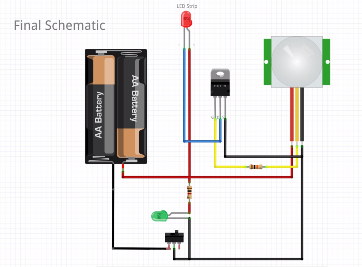
Step 2: Wiring up the LED Strip to the Motion SensorBelow is how you want to wire up the module with the MOSFET (transistor) in order for this project to operate. The N-Channel MOSFET being used is FQP30N06L.
Now the main part of this schematic involves the PIR Motion Sensor Module, the MOSFET and the LED Strip. First we supply 12VDC to the VCC Pin in the module and the (+) on the LED Strip (red wire). Next we use the MOSFET as an electrical switch to connect the LED to ground in order to turn it on. When the module senses motion, it outputs 3.3VDC to the Gate (Pin G on the MOSFET) and that will close the connection between the Source in Drain (Pin S and D on the MOSFET).
I added a switch and a status LED into this schematic as well. When the switch is OFF - nothing in the schematic is active and the Status LED is off. When the Switch is ON, the status LED will come on and the circuit is now active to take motion commands to turn on the LED Strip.
Step 3: Making an EnclosureNext, I wanted to keep all the electrical components within an Enclosure so there were no live wires accessible to the user. Basically I just used wood and stained it to the color of my furniture in my room.
I made the following holes in the enclosure:
1. Motion Sensor (front left)
2. On/Off Switch (front right)
3. LED Status Light (top left)
4. LED Connector Piece (top right)
5. Time Delay Knob Access (right)
Here is what the finished product looks like:
And Here is what the backing with the wiring looks like:
The Led Strips need to be cut so that you have access to the (+) and (-) pads on the strip that feed into the connector piece (see picture). At this point you should be able to supply the schematic circuit with 12VDC either from a plug-in power supply or from a battery supply - I used the 12VDC wall wart that came with the LED Strip. Now you can peel the backing of the LED Strips and stick them to the underside of your bed.
Once you have everything connected and powered on, you can flip the toggle switch on and your Status LED should come on right away. Next once your Motion Sensor senses motion your LED Strip should come on. If it doesn't you most likely have wiring problems as this project requires hardware and no software or programming. You can watch the video at the beginning of this tutorial for a better visual of this working. I go in depth on setting this project up as well.
The best part of this tutorial is that this is not just limited to your Bed, you can stick these LED Strips anywhere because they have their own adhesive. Put them in your closet when you open the door, in your drawers when you opened them, where ever! Get Creative and let me know if you have any questions!


Comments
Please log in or sign up to comment.