Add a splash of vivid colours💚💙🔴 to your next Arduino Project using RGB diffused LEDs. Welcome to another interesting Wokwi Arduino simulator example. In this example, you will connect an RGB LED to an Arduino UNO and drive it. To make this Arduino project interesting, you will also use three linear slide potentiometers to set the LED colour. Let us get started!🏃♂️
Wokwi Arduino SimulatorWokwi Arduino Simulator can be accessed here. We will use the Wokwi Arduino simulator as it is free, works directly out of the browser (no need to install or no admin permissions needed). Wokwi Arduino simulator supports RGB LED.
We will get to the basics of RGB LED, but before that let us look at the final simulation video📺 to see what we will build in this example.
In the link, you will get details📚 about the RGB LED as well as attributes associated with the RGB LED part. Attributes, in general, helps you to set various features of the part you are using. For example, in this example - The LED can be configured to act either like a Common Anode type or a common cathode type. You can buy🛒 the LED from the Adafruit site or any other site.
Depending on which pin you are driving and the relative proportions, You can change the brightness🌤☀⛅🌥🌞 as well the colour of the LED.
Building the RGB LED Arduino projectFollow these step 🦶 by step 🦶 instructions to complete the project quickly. For more details, you can read this article as well as more advanced features of the simulator.
Start New Project and add RGB LED
Start with an empty Arduino UNO project template. You can add the RGB part easily to the project.
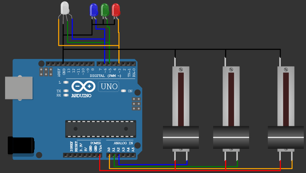
Add three slide potentiometers. you can click and drag ⛸the wokwi parts to move around.
Rotating 🤾♀️🤸♂️the component on the Wokwi Arduino simulator is easy. Just click on the item to select and press the R key on your keyboard.
You need the wires to connect the devices together. making connections between two junctions is as easy as two mouse clicks!
Use the small video in the introduction to find the schematics connections. If you follow the same connections, you can straight away use the code with no modifications. If you intend to take a bit challenging path, you can do different connections You have to update the code to suit your connections. Make sure you connect the LED pins to the PWM compatible Arduino Pins (the pins with ~ mark). You can skip the three coloured LEDs as they are not a must.
// RGB and R, G, B LED demo
// Wokwi Arduino simulator
// Link: https://wokwi.com/arduino/projects/306455554559050306
const int pinR = 3;
const int pinG = 5;
const int pinB = 6;
const int potR = A0;
const int potG = A1;
const int potB = A2;
void setup() {
pinMode(pinR, OUTPUT);
pinMode(pinG, OUTPUT);
pinMode(pinB, OUTPUT);
pinMode(potR, INPUT);
pinMode(potG, INPUT);
pinMode(potB, INPUT);
}
int readPot(int pin) {
return map(analogRead(pin), 0, 1023, 0, 255);
}
void loop() {
analogWrite(pinR, readPot(potR));
analogWrite(pinG, readPot(potG));
analogWrite(pinB, readPot(potB));
}https://wokwi.com/arduino/projects/309322156152455746
Comments and FeedbackPlease feel free to complete the project and share your project. I will be happy to add them to the article. Please suggest your feedback about the article and the simulator in the comments. I will reply to all the comments. You can find a cool growing community https://wokwi.com/discord. Share your interesting projects and browse through several curious projects from fellow developers and makers on Facebook Wokwi Group!


_ztBMuBhMHo.jpg?auto=compress%2Cformat&w=48&h=48&fit=fill&bg=ffffff)

_wzec989qrF.jpg?auto=compress%2Cformat&w=48&h=48&fit=fill&bg=ffffff)


Comments
Please log in or sign up to comment.