


Hardware components | ||||||
 |
| × | 1 | |||
 |
| × | 1 | |||
Software apps and online services | ||||||
 |
| |||||
What if I told you that your voice actually has a carbon foot print? That I could measure the amount of CO2 in your body if you drop some bars? Unfortunately, technology has not yet reached this state, BUT what we could actually do is use the same microphone in order to measure the change of air pressure, caused by the shaking of CO2 molecules inside a measurement chamber. Caught your attention huh? Stick with us in this protip and not only will you figure out how to use the mini CO2 sensor, but will also understand how it works.
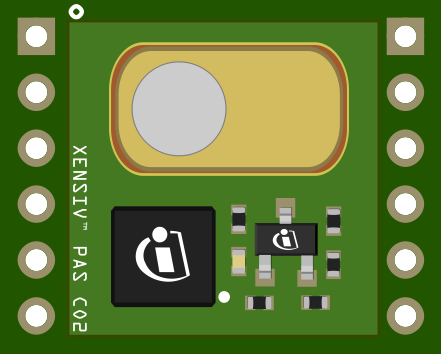
Hardware OverviewLet's have a closer look at what components are on the board and then we'll have a look at what the pins are used for and how to connect them to start sensing
The board consists of:
- Its own onboard microcontroller. This microcontroller runs the compensation algorithms and delivers direct ppm readouts of the CO2 levels. It supports interfaces of I2C, UART and PWM
- A MOSFET that drives the MEMS heater for the infrared source
- A port for gas diffusion (copper colored dome that's used to acoustically isolate the measurement chamber from the outside environment)
Underneath the Gas diffusion port, lie the MEMS microphone and the IR emitting source.
Wanna have a more interactive look at the 3D model of the board? Click here to check it out!
How the sensor works?Well here comes the fancy explanation: the PAS (short for Photo Acoustic Spectroscopy) principle works as follows: Pulses of light from an infrared source pass through the optical filter tuned specifically to the CO2 absorption wavelength (λ= 4.2 µm). The CO2 molecules inside the measurement chamber absorb the filtered light, causing the molecules to shake and generate a pressure wave with each pulse. This is called the photoacoustic effect. The highly sensitive MEMS acoustic detector detects the pressure change generated by CO2 molecules within the sensor cavity, and the readings of this microphone could be converted to CO2 concentration readings!
Check out this video to find out more! (It's just two minutes don't worry ;)
Pin Breakdown- 3.3V: 3.3V Supply Input
- RX: UART receive side
- SCL: I2C SCL (serial clock)
- TX/SDA: UART transmit or I2C SDA (serial data), depending on selected communication interface
- PWM DIS: PWM disable input (set high to disable PWM)
- PWM: PWM signal output
- PSEL: Communication interface selection
- INT: Interrupt output
- 12V: 12V supply input
- SWD: Serial wire debug data (keep NC)
- SWCLK: Serial wire debug clock (keep NC)
Disclaimer: When using this sensor board, don't forget to connect pull ups resistors to the I2C Communication Pins.Example Circuit Connections
The diagram above shoes an example on how to connect the sensor board to your microcontroller board of choice. (In the diagram the microcontroller being used is the XMC2GO)
Note: Pull up resistors should be about 10KOhmOperation Modes
Let's talk about how the sensor itself works. On a hardware level the sensor has three modes at which it operates:
•IDLE : The device does not perform any CO2 concentration measurement. The device remains inactive until it becomes active shortly to serve interrupts before going back to an inactive state.
•CONTINUOUS : In this mode, the device periodically triggers a CO2 concentration measurement sequence. Once a measurement sequence is completed, the device goes back to an inactive state and wakes up automatically for the next measurement sequence. The measurement period is programmable from 5sec to 4095 sec.
•SINGLE-SHOT : In this mode, the device triggers a single measurement sequence. At the end of the measurement sequence, the device goes back automatically to idle mode.
In addition to these hardware modes there are also two modes that are achievable by using the library provided which are:
Alarm mode: If the alarm threshold argument is non-zero, the alarm mode is activated, and the sensor internal flag will be enabled if the concentration of CO2 goes above the specified value. This option is better combined with the interrupt mode. Thus, if the interrupt mode is available and a callback function is passed, the interrupt will occur only when the co2 concentration goes above the threshold. This makes mostly sense for continuous measurement configuration. But it can be used as well for a single shot configuration
Early notification: The early notification mode can be used for battery power solutions. The interrupt signal can trigger the enablement of the 12V emitter power supply just before the measurement is performed, and switch it off as the interrupt signal is disabled. Therefore, the power supply 12V only needs to be on during the CO2 sensing. (Note in case of the early notification mode the callback fed in the startMeasure() function is executed every time that the sensor is about to start performing the measurement and when it is completed.When this flag is set, the alarm interrupt functionality is not available. Both options cannot be combined.
For both alarm and early notification mode you will have to connect the interrupt pin of the mini board with the interrupt pin of your microcontroller. (for example if you would be using the XMC2GO then that would be pin 9)
Check out our XMC For Arduino Page by clicking here!
SoftwareNow that we're familiar with our system, let's look at how we could actually use it. First thing's first - let's install all the software needed:
- Install Arduino IDE. If you are new to Arduino, please download the program and install it first.
- Install the sensorlibrary. In the Arduino IDE, go to the menu Sketch > Include library > Library Manager. Type pas-co2-sensor and install the library.
Now that we've got all the prerequisites in check, let's dig in!
Arduino code generally consists of two parts: a dynamic and a static part.
The static part or "the skeleton" as I like to call it: is just the part where all the initialization is done and we tell the Arduino essentially what it's connected to. The skeleton part is ran only once and then the Arduino jumps onto the dynamic part.
The dynamic part is the part, where we tell the Arduino "Hey I need you to do this and that, and in case of a certain scenario maybe do this" and so on. It's the part where we explicitly instruct the microcontroller to do stuff. This part is continuously ran by the Arduino, as long as there's power delivered to the microcontroller.Skeleton Code:
For using our library we need to always include it along with the basic Arduino library at the top of our code:
#include <Arduino.h>
#include <pas-co2-ino.hpp>
Additionally we will have to instantiate an object of type PASCO2Ino to define our desired sensing functionality, let's say we'll call it cotwo:
PASCO2Ino cotwo;However, if you want to use the early notification mode/alarm mode you'll have to tweak the object instantiation just a little bit :), all you'll have to do since we'll be dealing with an interrupt pin is to instantiate by extra giving in the Wire Instance and interrupt pin. Do this by simply writing:
PASCO2Ino cotwo(&Wire, 9);The 9 in the snippet above is just the interrupt pin number on the XMC2GO feel free to change it dependent on your microcontroller that you want to use.
The last step to do before getting our hands dirty is to create an error type variable and a 16 bit integer to store our sensor readings. (The error type variable will be used as an error monitoring buffer, where we will be monitoring its value to make sure that everything is working properly):
int16_t co2ppm;
Error_t err;
By now the question that we have to ask our self is: How do we actually want the sensor to talk to us? To answer that we would have to look at our communication systems.
Forthe connection to the sensor weuse I2C andsimply initialize itby:
Wire.begin();
Wire.setClock(400000);
(In the code snippet above I used a frequency of 400000 since it is the maximum frequency that the sensor supports.)
To use UARTin order to read from your microcontroller onto your computersimply initialize an UART interface by:
Serial.begin(9600);Next step is to actually initialize our sensor, we do this by using the begin( ) function on our created instance of the PASCO2Ino object we created. This is where the error type variable itself comes in handy. We will use it to check that the initialization was performed successfully:
err = cotwo.begin();
if(XENSIV_PASCO2_OK != err)
{
Serial.print("initialization error: ");
Serial.println(err);
}
Take a look at the table below, where you could find all 8 Error Macros and what the error indicates.
AND NOW to the most important function of the library startMeasure( ), this function is what dictates the whole functionality of our sensor. The input parameters of this function decide the mode used where:
- single shot mode: no input parameters
- Even if you call the function that reads out the CO2 level, it will only read zero
An example for using startMeasure( ) for single shot mode:
cotwo.startMeasure();- continuous mode: input of the function is ameasuring interval in seconds
An example for using startMeasure( ) for continuous mode, where the sensor captures CO2 values every 10 seconds:
cotwo.startMeasure(10);- alarm mode: first input is the measuring interval in seconds, in second place is the PPM threshold and at last a pointer to the callback function for the interrupt
An example for using startMeasure( ) for alarm mode captures CO2 values every 10 seconds. It triggers an interrupt when the CO2 concentration reaches 1200ppm and calls a function named isr:
cotwo.startMeasure(10,1200,isr);- early notification mode: first input is the measuring interval in seconds, the PPM threshold is per default 0, the pointer is again to the callback function for the interrupt and with "true" in the last position the early notification mode is enabled
An example for using startMeasure( ) for early notification mode, where the sensor captures CO2 values every 10 seconds, and triggers an interrupt function (isr) everytime the sensor is about to start performing the measurment and when it is completed:
cotwo.startMeasure(10, 0, isr, true);Note: Always Keep in Mind that the minimum measuring interval is 5 secondsDynamic Code
The second most important function is the getCO2( ) function. This function takes in our 16 bit integer variable that we created earlier, stores the new CO2 PPM value and then gives back an error type value.
As shown in the table above, the returned error checking variable if no error is detected is XENSIV_PASCO2_OK or 0. To be safe we check the error variable with an if condition when we use the getCO2 function to read out the CO2 value.(Just like in the code below)
err = cotwo.getCO2(co2ppm);
    if(XENSIV_PASCO2_OK != err)
    {
      Serial.print("get co2 error: ");
      Serial.println(err);
    }

    Serial.print("co2 ppm value : ");
    Serial.println(co2ppm);
This makes debugging easy, because then you could just sit back and relax and assume that everything is working perfectly as long as the microcontroller is spitting out Co2 ppm values. You could also connect a red LED for example to your board and light it up in the if condition, so that if something goes wrong you have your notice, without relying on a connection to a serial monitor.
Please make sure to have the object instance of the type PASCO2Ino initialized before performing any of these functions on it by using the begin( ) function!
Feel free to also check out the example code files provided by the library where there are 6 out of the box example codes:
- alarm-nofitication: Readout of the sensor CO2 concentration based on threshold crossing and synched via hardware interrupt
- continuous-mode: Readout of the sensor CO2 concentration value using continuous measurement mode
- device-id: Readout of the sensor devices product and revision identifiers
- early-notification: Readout of the sensor CO2 concentration based on early notification synched via hardware interrupt
- forced-compensation: Set CO2 reference offset using forced compensation
- single-shot-mode: Readout of the sensor CO2 concentration value using single shot measurement mode
Also check out the other variants of the PASCo2 Sensor board :) Click here to learn more!


Comments