

Hardware components | ||||||
 |
| × | 1 | |||
 |
| × | 1 | |||
 |
| × | 1 | |||
 |
| × | 1 | |||
 |
| × | 1 | |||
 |
| × | 1 | |||
 |
| × | 1 | |||
| × | 1 | ||||
| × | 2 | ||||
| × | 1 | ||||
| × | 1 | ||||
| × | 2 | ||||
| × | 1 | ||||
| × | 1 | ||||
| × | 1 | ||||
| × | 1 | ||||
Software apps and online services | ||||||
| ||||||
Hand tools and fabrication machines | ||||||
 |
| |||||
 |
| |||||
 |
| |||||
Couple of things to begin with. As for me, I enjoy gardening. Living in a rental apartment on the third floor with a north and west facing balcony, that’s a bit of a challenge. What I need is a greenhouse. It requires precise plant care and a good atmosphere for them to grow strong and healthy. Too much watering and you’re going to drown them, to less water and they will dry out. They need the right lighting and a suitable temperature. There are many tasks to attend to, even for those who may be inclined to laziness.
The “smart greenhouse” should be able to eliminate all the “care work”. Let me guide you through the developing and building process, then let’s wire everything up and give it a first try with fresh seedlings for a start.
ConceptFour systems need implementation. A lighting system, a watering system, a heating system and an air flow system. The greenhouse includes a CO2 sensor, a soil moisture sensor and a temperature sensor. In the concept picture below you can see the automated watering system, lighting control, temperature control and air exchange system. All of these components work together to create an optimal growing environment for plants.
The Infineon PSoC™ 6 Wi-Fi BT Prototyping Kit CY8PROTO-062-4343W functions as the master device, programmed using Micropython. Additionally, the setup requires the Infineon Profet Arduino Shield as a high-side switch, along with two buck converters (EVAL_TDM3883_3.3Vout and TLS412033V COREBOARD TOBO1) to adjust the voltage levels. This includes shifting the voltage from 12 volts to 3.3 volts for the water pump and to 5 volts for the power supply of the PSoC6 prototyping kit.
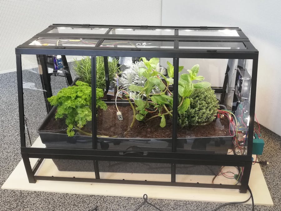
The PSOC6 prototyping kit incorporates an I2C channel, facilitating the reading of sensor values and control of the LED shield. The utilization of I2C is ideal for this application, given its compatibility with short cable lengths and low-speed communication requirements. In the accompanying image, a side view of the green house showcases the arrangement of all the mentioned components.
Watering system
Two modes should be available: timed watering and watering, when the soil is too dry. For this purpose, the system uses the Adafruit Stemma moisture sensor and the RTC module of the PSoC6 kit.
A centrifugal water pump is used to pump the water from the tank through a hosepipe into the greenhouse, where it is spread around in the soil.
You can purchase a small and quiet water pump for 65€. The link to purchase can be found in the hardware list above. A hosepipe that is resistant to corrosion and strong enough to withstand the 200 milli bars of pressure generated by the water pump is also listed there.
Plant health
The greenhouse implements the PASCO2-SHIELD2GO to check the health of the plants. The approach is simple. Using the sunlight, healthy plants perform photosynthesis, converting carbon dioxide and water into oxygen and glucose. If the CO2 value drops, the plants are doing fine. If it drops below a certain level, you can automatically activate the fans to bring fresh air and more CO2 back into the greenhouse. For more information on the PSOC6 board and the PASCO2go sensor shield operated by MicroPython, please visit the following article.
Air Flow System
The SHIELD_BTS7002-1EPP high-side switch regulates two fans via its output channel, which is controlled by the GPIO pin of the PSOC6 board. This Arduino Shield is powered by the power adapter and can support loads up to 2 amperes. The fans are intended to be activated when the air quality deteriorates, ensuring an effective air exchange. Key indicators for air quality include humidity, temperature, and the CO2 level. It is uncertain whether there will be significant fluctuations in the CO2 level over a short period. To ensure the ideal environment for your plants, experiment with the threshold values.
Lighting
Plants typically require adequate sunlight to grow robustly. The plants in this indoor greenhouse need additional lighting to receive at least 12h – 16h of light. To fulfill this requirement the green house has a LED strip which is powered by the KIT_XMC_LED_DALI_20_RGB LED Arduino Shield. The PSOC6-Board’s internal RTC-Module is used for timing and coIntrols the LED shield via I2C.
Temperature control
To maintain a temperature of 15°C – 20°C in both soil and air, two heating foils can be utilized. Both are connected to the second output channel of the SHIELD_BTS7002-1EPP in the same way as the fans. The Adafruit STEMMA Soil Sensor as well as the SHT35 Temperature & Humidity Sensor can measure temperature. Both communicate over the I2C bus.
Hardware SetupNow connect all the components as shown in the figure below. To get a better look at the wiring plan open the PDF document attached. Start the hardware setup by connecting the 12V power line from the Power adapter with the heating, SHIELD_BTS7002-1EPP and the KIT_XMC_LED_DALI_20_RGB Arduino Shield. Connect the input channel of the 3.3V Buck converter to 12V and the water Pump to its Output. The PSOC6 board and the 5V Pin of the PASCO2 Shield2go must be connected to the Output of the 5V Buck converter.
Now connect the PSOC 6 board’s GPIO pins to the input channels of the SHIELD_BTS7002-1EPP as shown in the figure below. P9_5 controls the heating, P9_3 the water pump and P8_5 the two fans.
Connect the I2C bus to finish the wiring. Therefore, use the SCL and SDA pins of the PSOC6 Board 6_0 and 6_1 as a serial clock and serial data line. Power the sensors, using the P6VDD and GND pins. Use JST-Crimp connectors, to ensure a proper connection and a stripboard to solder the cables. A housing can be made with FDM 3D Printing. The figure below shows the detailed wiring for the I2C bus of the sensors.
The LED shield can be connected as shown in the following picture.
Mount the PCBs to a window on the side of the greenhouse. Use the attached CAD-Files for guidance. The windows can be modified with a Laser cutter.
Find the modified window on the left hand side and the mounted fan and PCBs on the right hand side. Everything is mounted with M3 screws and screwnuts to the window. Consider using a thicker material (e.g. Polymethylacrylate 3mm – 4mm) than IKEA uses for the windows, to reach better stability. In the next picture you see the greenhouse side view with all the components.
The last part of the Hardware section is the watering system, including the tank, water pump and a hosepipe. Find the CAD file attached.
The pictures above show the water tank, the hosepipeconnection the mounting hole and the finished water tank.
The water pump is shown in the next picture below. There is an M2.5 mounting hole on the backside of the Pump. Use an M2.5x10 screw, to fasten it to the water tank. The water pump is quiet and small, making it ideal for the application. It requires a 3.3V power supply to operate efficiently.
You will need to drill holes in two flowerpots, to arrange the hosepipe. In order to spread the water around your plants, poke multiple small holes into your hosepipe. To complete the hardware assembly, glue the LED strip to the inside of the upper frame of your greenhouse.
Libraries
Micropython is the dedicated programming language for this project. Infineon has provided a library for micropython on the PSOC6 board. To install and set up MicroPython, we already have a protip here. After installing the MicroPython library, you must install the following libraries as well.
- Adafruit SHT35
- STEMMA Soil sensor
- LED Shield
I2C Setup
Now everything is set to start developing your code. The class Init provides the methods to initialize the required pins on the PSOC6 board, set up the I2C connection, and initialize the sensors and the lighting shield.
import time
from machine import Pin, I2C, RTC
class Init:
def init_I2C():
i2c = I2C(0, scl='P6_0', sda='P6_1', freq = 400000) # Correct I2C pins for PSOC6
return i2c
RTC Setup
You will need a method for initializing the rtc module. Therefor you could use you could use e.g. the laptop time. Create a new python file and implement the class RTCManager, in which you will define the two methods get_pc_time() and init_rtc(pc_time).
import time
from machine import RTC
class RTCManager:
The method get_pc_time() uses the timestamp of your computer, and converts the given time into a tuple, which is handed over to the RTC module.
def get_pc_time(self):
'''Gets the current date time of the laptop and converts it to a matching tuple for the RTC-Module of PSOC6.
Returns this tuple in the correct order (year, month, mday, weekday, hour, minute, second, millis).'''
today = time.localtime()
year = today[0] + 1900
month = today[1] + 1
mday = today[2]
hour = today[3]
minute = today[4]
second = today[5]
weekday = today[6]
return (year, month, mday, weekday, hour, minute, second, 0)
Now define the init_rtc(pc_time) method. Hand over the formatted PC-Timestamp and initialize the PSOC6 internal rtc. It returns a RTC object.
def init_rtc(self, pc_time):
'''Initializes the RTC module of the PSOC6 board with the current date time of the laptop.
Returns RTC object.'''
rtc = RTC()
rtc.init(pc_time) # Initialize RTC with specific date and time
return rtc
With that done, you can start to write the DataManager class where all measurement methods are implemented.
Sensor measurement
The class DataManager includes all sensor measurements such as CO2 levels, soil moisture, soil temperature, humidity, and air temperature..
The ambient_measurement() needs the sensor Objects as an input and forms a tuple with the measured sensor values.
def ambient_measurement(self, co2Obj):
'''this method gets all the measurable ambient values,
packs the into a tupel (ambient values) and returns that tupel as the following:
ambient_values[0] = co2ppm
ambient_values[1] = soil_moisture
ambient_values[2] = soil_temperature
ambient_values[3] = humidity
ambient_values[4] = air_temp
'''
#get CO2 Value
co2ppm = co2_read_sensor_data(co2Obj)
#get soil moisture and temperature
soil_moisture = seesaw.get_moisture()
soil_temperature = seesaw.get_temp()
#get humidity and air temperature
sht_value = sht.get_measurement()
humidity = sht_value["humidity"]
air_temp = sht_value["temp_celsius"]
#pack the tupel and return ambient values
ambient_values = (co2ppm, soil_moisture, soil_temperature, humidity, air_temp)
return (ambient_values)
The method daylight_control() measures the current time, given by the rtc module and sets or resets the variable dayflag and daylight. According to this, it switches the lights on or off.
def daylight_control():
'''Gets the current time, interprets the hour, and switches the lights based on the time of day'''
thistime = rtc.now() # Returns tuple with year, month, day, hour, minute, second, millis
thishour = thistime[4] # Fifth element of rtc tuple is the current hour (0-23)
global dayflag # Initialize dayflag
global daylight # Initialize daylight
# Interpret the current time and set or delete the dayflag
if (thishour > 7) and (thishour < 19): # Using logical AND instead of bitwise AND
dayflag = 1
else:
dayflag = 0
# Switch the light on and off based on the time of day
if (dayflag == 1) and (daylight == 0):
board.light_on()
daylight = 1
elif (dayflag == 1) and (daylight == 1):
daylight = 1
elif (dayflag == 0) and (daylight == 1):
board.light_off()
daylight = 0
else:
daylight = 0
Next we need to implement a helper method to read the co2 Data.
def co2_read_sensor_data(co2Obj):
''' Helper function to read sensor data
Args : co2Obj - Sensor Object
Returns: Co2 Value in Parts per million as an int
'''
# wait for the value to be ready
time.sleep(10)
#get co2 values
co2ppm = co2Obj.get_co2_value()
if co2ppm == -1:
print("[co2-module] : Measurement not ready yet")
else:
print("[co2-module] : co2 ppm value: ", co2ppm)
return co2ppmBefore implementing the main method, you probably want to visualize the sensor data. The Hackster-Article, mentioned earlier provides the required information for your cloud set-up. Download the secrets file and configure your network and cloud details as described in the sections “cloud setup” and “run the demo code”. Then implement the following two methods in your main class.
def database_connect() :
''' Helper function to connect to IoT Cloud platform'''
from umqtt.simple import MQTTClient
client = MQTTClient(client_id=b"Psoc6",
server=b"io.adafruit.com",
port=0,
user=s.username,
password=s.adafruitIOKey,
keepalive=7200,
ssl=True,
ssl_params={'server_hostname':'io.adafruit.com'}
)
status = client.connect()
if not status:
print("[db-module] : Connection to adafruit.io successful!")
return client
def stream_sensor_data_to_cloud(ambient_values, dbObj):
''' Helper function to read sensor data and stream to cloud DB
Args : co2Obj - Sensor Object
dbObj - Database Object
Returns: None
'''
# wait for the value to be ready
sleep(2)
# Stream data to IoT cloud
dbObj.publish(s.pubTopic,b'{"value":' + str(ambient_values) + '}')The last thing you need to do is calling all the methods in your main loop, implemented in the class Main and implement a couple of if/else statements, to get the greenhouse running.
import time
from machine import Pin, I2C, RTC
from sht3x import SHT3X
import stemma_soil_sensor
import seesaw
import pasco2 as sensor
import led_lighting_shield
from rtc_manager import RTCManager
from init import Init
Set the starting time and initialize the rtc module.
#init RTC
current_time = RTCManager.get_pc_time()
RTCManager.init_rtc(current_time)
Initialize the I2C channel and your sensors, create an object for each one of them.
#init I2C, generate I2C object as well as sht35 and stemma soil sensor!
i2c = Init.init_I2C()
sht = sht3x.SHT35(i2c)
seesaw = stemma_soil_sensor.StemmaSoilSensor(i2c)
Initialize the LED lighting shield and create an object.
#init LED Shield
led = led_lighting_shield.LEDLightingShield(i2c)
Initialize your actuators such as fans, water pump and heating foil and create an object for each one of them.
#init Pins
fan = Init.init_fans()
pump = Init.init_pump()
heat = Init.init_heat()
Inizialize the co2 sensor and create an object.
#init pasco2, generate co2-Object
pasco2 = Init.co2_sensor_init()
time.sleep(10)
Set the threshold values. These are the target values for your plant environment. Experiment with them to create the optimal environment for your plants. The soil moisture value ranges from 200 (verry dry soil) to 2000 (completely drained). The threshold is set to 1000 in our case, but it can vary significantly between plants.
#set threshold values
target_minsoil_moisture_threshold = 1000
target_max_humidity = 70
target_maxair_temperature = 30
target_minair_temperature = 12
target_minsoil_temperature = 10
target_co2 = 600
Now define the endless loop. Call the methods, that you defined earlier and use an if/else statement, to control the actuators.
def __main__():
DataManager.daylight_control()
ambient_values = DataManager.ambient_measurement(pasco2)
stream_sensor_data_to_cloud(ambient_values, dbObj)
if (ambient_values[0]<target_co2) | (ambient_values[3]>target_max_humidity) | (ambient_values[4]>target_maxair_temperature) :
fan.high()
else
fan.low()
#soil moisture and watering system
if ambient_values[1]<target_minsoil_moisture_threshold:
pump.high()
else
pump.low()
#soil temperature and air temperature
if (ambient_values[2]<target_minsoil_temperature) |(ambient_values[4] < target_minair_temperature) :
heat.high()
else
heat.low()
time.sleep(2)
if name == "__main__":
main()
Greenhouse Dashboard
In the end, it would be cool to see the data our sensors deliver. Checking the wellbeing of your plant is then possible in real time. Let’s create a dashboard showing the data we are interested in.
To get things running, start by importing the microdot web server library with these commands after installing the necessary files on your PSoC 6 device.
from microdot_asyncio import Microdot, Response, send_file
from microdot_utemplate import render_template
You need microdot.py , microdot_utemplate.py, microdot_asyncio.py, recompile.py and the folders static (containing main.js and style.css) and templates (containing index.html and index_html.py).
Define two variables for your network connection (SSID and Password) and then define a new method for establishing the connection to your network.
# Replace the following with your WIFI Credentials
SSID = "Psoc6Web"
SSI_PASSWORD = "CY8CPROTO#062#4343W"
def do_connect():
import network
sta_if = network.WLAN(network.STA_IF)
if not sta_if.isconnected():
print('connecting to network...')
sta_if.active(True)
sta_if.connect(SSID, SSI_PASSWORD)
while not sta_if.isconnected():
pass
print('Connected! Network config:', sta_if.ifconfig())
print("Connecting to your wifi...")
do_connect()
Once connected to the wifi the thonny Shell should look like this:
The line “Network config” shows the IP-Adress of your device which is marked in red, in the picture above.
A couple of further adjustments are required, to get the webserver and the dashboard running.
Initialize an app object with the following commands.
app = Microdot()
Response.default_content_type = "text/html"
Define an index request method and the get_sensor_readings method, which are both an async def type. This will make shure that the device is able to handle those methods simultaneously. Wrap the get_sensor_readings method around your main functionalities. Use the following code as an example.
@app.route("/")
async def index(request):
return render_template("index.html")
# Read sensor readings and return as JSON
@app.route("/sensorReadings")
async def get_sensor_readings(request):
drained = 0
waterhour = 0
ambient_values = DataManager.ambient_measurement(pasco2,seesaw,sht)
if ambient_values[0] ==-1:
co2 = ambient_values[0]
else:
co2 = ambient_values[0]
last_co2 = co2
if co2 == -1:
co2 = last_co2
print ("co2",co2)
soil_moisture = ambient_values[1]
soilmoisture = (soil_moisture/2000)*100
print ("soil_moisture = ",soil_moisture)
humidity = ambient_values[3]
print ("humidity = ",humidity)
temperature = ambient_values[4]
print ("temperature",temperature)
brightness = 500
sensor_readings = {"status": "OK", "temperature": temperature, "co2": co2, "humidity": humidity, "soilmoisture": soilmoisture}
#main loop here:
#check time for daylight control
DataManager.daylight_control(rtc,daylight,led)
#read sensor data
ambient_values = DataManager.ambient_measurement(pasco2,seesaw,sht)
print (ambient_values)
if (ambient_values[0]<target_co2) or (ambient_values[3]>target_max_humidity) or (ambient_values[4]>target_maxair_temperature) :
fan.high()
else:
fan.low()
#hydration system
Hydrate.hydration(drained, waterhour,target_minsoil_moisture_threshold,pump,pasco2,seesaw,sht)
#soil temperature and air temperature
if (ambient_values[2]<target_minsoil_temperature) or (ambient_values[4] < target_minair_temperature) :
heat.high()
else:
heat.low()
return sensor_readings
Further we need the methods shutdown and static.
# Shutdown the application
@app.route("/shutdown")
async def shutdown(request):
request.app.shutdown()
return "The server is shutting down..."
# Static CSS/JSS
@app.route("/static/<path:path>")
def static(request, path):
if ".." in path:
# directory traversal is not allowed
return "Not found", 404
return send_file("static/" + path)
Type the start command, which will set up the server, which enters an endless listening loop, updating the shown sensor values in the dashboard.
app.run()Now your all set. Connect your mobile phone or laptop/ tablet to the same network and type the IP Adress followed by :5000 which is the desired port number, into your web browser. In this case it would be:
http://192.168.43.151:5000
Once connected and loaded, the dashboard should look like this.


Comments