A bundle of electrical conductors used for carrying electricity is called as a cable. A under ground cable generally has one or more conductors covered with suitable insulation and a protective cover.
Commonly used materials for insulation are varnished cambric or impregnated paper. Fault in a cable can be any defect or non-homogeneity that diverts the path of current or affects the performance of the cable. So it is necessary to correct to correct the fault.
Power Transmission can be done in both overhead as well as in underground cables. But unlike underground cables the overhead cables have the drawback of being easily prone to the effects of rainfall, snow, thunder, lightning etc. This requires cables with reliability, increased safety, and ruggedness and greater services. So underground cables are preferred in many areas especially in urban places. When it is easy to detect and correct the faults in overhead line by mere observation, it is not possible to do so in an underground cable. As they are buried deep in the soil it is not easy to detect the abnormalities in them.
Even when a faults is found to be present it is very difficult to detect the exact location of the fault. This leads to debugging of the entire area to detect and correct the fault which in turn causes wastage of money and manpower. So it is necessary to know the exact location of faults in the underground cables.
Whatever the fault is, the voltage of the cable has the tendency to change abruptly whenever a fault occurs. We make use of this voltage across change resistors to detect the fault.
In the event of short circuit (Line to Earth) fault, the voltage accordingly. It is then fed to an ADC to develop precise digital data that is directed to the programmed Arduino to display the same in kilometers. Hence this paper is very helpful for determining exact location of short circuit fault.
This project is to determine underground cable fault using specific application. If the short circuit or any physical damage is occurred then the voltage across cable line changes. The changes which occurred can be calculated using CT theory. CT theory provide simple and accurate means of sensing current flow in power conductors. Signal conditioner manipulates the analog signal for the further processing.
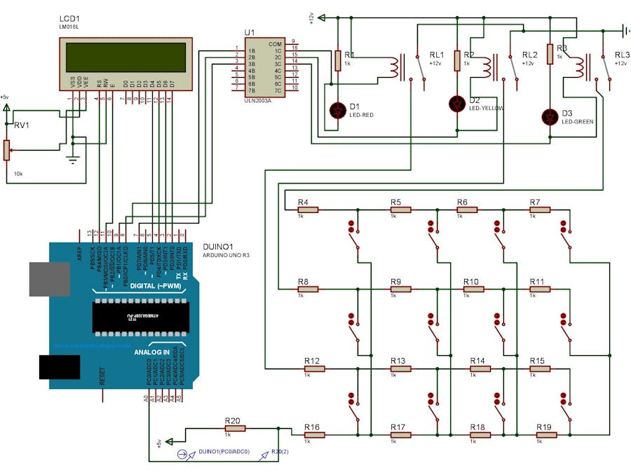
In this circuit we are used an Arduino UNO, Relays, ULN2003A, LCD, LEDs, Switches.
ULN2003 is a high voltage and high current Darlington array IC. It contains seven open collector Darlington pairs with common emitters. A Darlington pair is an arrangement of two bipolar transistors.
ULN2003 belongs to the family of ULN200X series of ICs. Different versions of this family interface to different logic families.ULN2003 is for 5V TTL, CMOS logic devices. These ICs are used when driving a wide range of loads and are used as relay drivers, display drivers, line drivers etc.
Each channel or Darlington pair in ULN2003 is rated at 500mA and can withstand peak current of 600mA.
The objective of this project is to determine the distance of underground cable fault from the base station in kilometers. An underground cable system is quite common in many urban areas wherein it becomes very difficult to repair in case of any faults because finding the exact location of the fault in such cable system is quite difficult. With the proposed system, finding the exact location of the fault is possible.
This project uses a standard concept of Ohms law, i.e., when a low DC voltage is applied at the feeder end through series resistor (assuming them as cable lines), then the current would vary depending upon the location of the fault in the cable. In case of a short circuit (line to ground), the voltage across the series resistors changes which is then fed to an ADC, to develop a precise digital data that gets displayed on the LCD.
The project is assembled with a set of resistors representing cable length in km and fault creation is made by a set of switches at every known km to cross check the accuracy of the same. The fault that occurs at a particular distance of a particular phase is displayed on the LCD interfaced to the microcontroller.
Furthermore, this project can be enhanced by using a capacitor in an AC circuit to measure the impedance which can even locate an open-circuited cable, unlike short circuited fault only using resistors in DC circuit as followed in the above proposed project.


_ztBMuBhMHo.jpg?auto=compress%2Cformat&w=48&h=48&fit=fill&bg=ffffff)


Comments