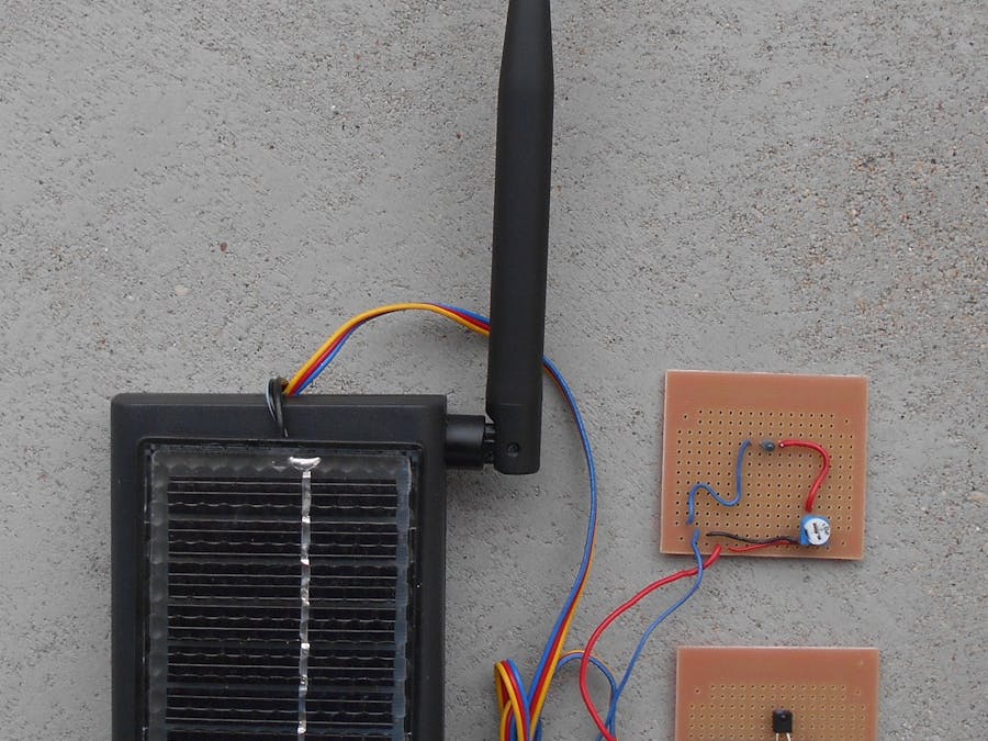
Device iot-postbox is used to detect new letter in postbox. When new letter in postbox was detected device send e-mail to user. Device use rechargeable batteries charged by solar panel. Microcontroller cc3200 is optimized for power consumption ( hibernation mode is used ).
hardware
Device iot-postbox based on cc3200 Launchpad module. New letter in postbox is detect by optical barrier building from transmitter IR (L-934SF4BT - 3mm, 880nm, 7mW) and photorezistor (QSE113 – 50˚, 880nm). Launchpad module is supply from two rechargeable AA batteries ( voltage 1.2V capacity 2500 mAh of each ). Batteries are charged by solar panel (voltage 3V, current 80mA). Module LaunchPad and batteries are mounted in Z-44 box (dimension 150 mm /80 mm /33 mm). Additionally external Wi-Fi antenna is mounted ( TRF1002 – 2,4GHz, 5dBi). Device iot-postbox is shown on picture 1.
Batteries are connected in series and battery cell is created ( 2.4 Volt, 2500 mAh ). On the output two capacitors are mounted ( battery dropout protection ). Solar panel is connected to batteries via diode. Optical barrier should be mounted inside postbox. Potentiometer regulate barrier work range and IR diode current. Photo tranzistor output is connected with cc3200 P08 input. Schematic is shown on figure 1.
Before you start work with iot-postbox you must make changes in cc3200 LaunchPad module. Diodes D1 and D4 must be removed (lower power consumption ) and external Wi-Fi antenna must be mounted. In default internal ( mounted on PCB ) antenna is used. You must change connection to external antenna. In this case resistor R111 should be removed and in R110 resistor place new connection should be created. After that you should connect to U.FL input external Wi-Fi antenna. How change antenna connection is shown on figure 2.
functionality
After power on all microcontroller modules are initialized ( UART, Watchdog, Hibernation ). Next cc3200 is set to work in hibernation mode. In hibernation mode cc3200 stay until new letter in postbox occur ( optical barrier brake, falling edge on P08 input - change from high state to low state ). After wake up from hibernation cc3200 is connecting to Access Point is logging to GMAIL server and is sending e-mail to recipient. After that cc3200 is setting in hibernation mode. New letter in postbox wake up microcontroller. Working cycle is repeating. Full iot-postbox work cycle is shown on figure 3.
hibernation
In iot-postbox device hibernation mode is used ( in this mode cc3200 current is only 4uA). Signal change on specific input can wake up microcontroller from hibernation. In iot-postbox device input number 17 ( P08 ) was used ( input connected with photoresistor output ). During normal work on P08 input is high state. When optical barrier is breaking ( new latter in postbox ) state is changing from high to low. In this moment cc3200 is waking up from hibernation mode.
Device iot-postbox sends e-mails to user using GMAIL services ( you must have active e-mail account in GMAIL service ). Microcontroller cc3200 connecting to GMAIL server, logging to user account and using SMTP protocol send e-mail to recipient. In project properties ( file configure.h ) you must set yours GMAIL account name and password, and recipient e-mail address. Additionally on you GMAIL account ( security tab ) you should enable access to less secure apps. With option you should choose is shown on figure 4.
software
Project was made in CCSv6. Software was written in C language. In project iot-postbox freeRTOS and SMTP client library are used ( libmail from SDK /netapps/smtp/client ). In thread system (file system.c ) two procedures HibernateEnter and EmailSendTask are called. In procedure HibernateEnter hibernate mode is activated. In procedure EmailSendTask is created connection with Access Point and is activated e-mail sending procedure. In procedure are configured GMAIL server parameters ( SMPT port number, server IP address, method of transmission coding, transmission coding algorithm ) and are set GMAIL account address and password. Additionally in procedure are set recipient e-mail address, message subject, and e-mail message text.
In project you can activate Watchdog module ( timer of work equal 50 seconds). Watchdog protect iot-postbox device against hang up.
start
Iot-postbox source code is available on github. You should download code and configure device parameters. In configure.h file you should set Access Point SSID name, password and you should define transmission coding algorithm. Additionally you should set GMAIL account name and password. Finally you should define recipient e-mail address. If you want activate Watchdog module you should open project options tab Predefined Symbols and from Undefine NAME you should delete value WATCHDOG_ON. After that in Pre-define NAME you should add value WATCHDOG_ON. After all changes you should rebuild project (Project -> Build All). Binary file iot_postbox.bin will be created. Using CCS UniFlash application you should program S-FLASH memory.
After that you should mount in postbox elements of optical IR barrier. Using potentiometer you should calibrate barrier range ( for example: for 100Ω barrier range is about 4 centimeters and current is about 7 mA ). Finally you should mount iot-postbox. Example of implementation is shown on picture 3.
Lukasz Krysiewicz, Poland


Comments
Please log in or sign up to comment.