Grove Mate - A simply and low cost little tool for you to get the analog or digital value of your Grove sensor in seconds, no PC and coding required, quick and straight.
StoryTesting the sensor is the very first step when we start to build a new arduino interactive project using sensors.
If you are a fans of open source hardware, you may have dozens of sensors in your drawer, and everytime you want to make use of them, you need to test them one by one to make sure whether it is a analog or digital sensor, or it is still in good condition, as well as how the analog value will change for different condition.
The most common way of doing that is to write a program which to read the pin value and "Serial.print" to the serial monitor or display the figure on display equiment such as digital display tube or OLED. Well, it at least cost you a development board, a grove shield, and your valuable time to write that code, oh, and you also need to finish the work with a PC.
In a word, this is a high frequency scene and we don't even have a simple tool to save time and energy for us. Therefor I made this simple grove sensor tester to fulfill the requirement, which you could get the analog or digital value of your grove sensor in seconds, and no PC and coding required.
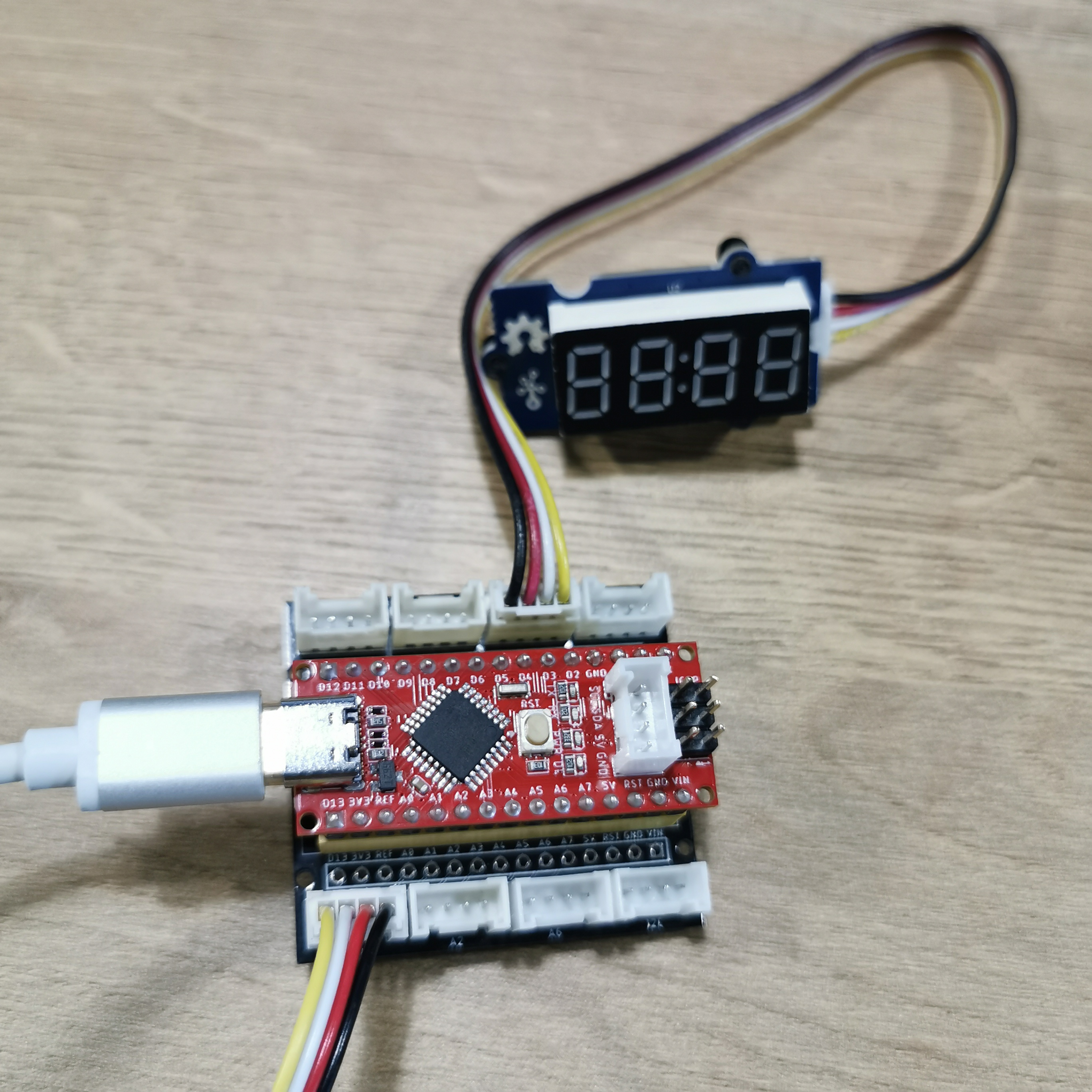
Step 1: Connect the HardwaresConnect Seeeduino Nano to the Grove Shield
Connect 4-digit Display to PIN 6 and 7 on Grove Shield
Connect a 4 pin grove cable to A0 (which you could connect any grove sensor you need to test)
I use CAD to design a box, attached you could find the.dxf file. I make it bigger than it should be, since I want to make more space to contain the cable. You could remove the cable by soldering it to the board and modify the design file to make a much more compact and decent shell. After laser cutting, to assemble the parts using acrylic glue, leaving the back side opened to put the hardware in.
For analog sensor, the value range from 0-1023, while the digital sensor value is 0 or 1.
Normally we use analogRead() to read analog sensor while digitalRead() to read digital sensor. In fact, we could use analogRead(Pin) to detect both analog and digital sensor, but when we doing so and print the sensor output to the serial monitor, you will get from a digital sensor the value 0 or other value(which indicates 1).
To reduce this confusion, I add a switch sensor to A2. When switch to HIGH, program uses analogRead() to read sensor and serial print analog sensor value. When switch to LOW, program uses digitaldRead() to read sensor and serial print digital sensor value which is 0 or 1.
If you don't have a switch, it is also fine just using one mode to detect both analog and digital sensor.
Upload the Program to your Seeeduino Nano via USB cable.
Step 4: Sensor TestingNow connect a sensor to A0, you will see the analog value display on the tube. Change the condition of the sensor and see if the figure changes. You could also open the serial monitor to see the data outprinted, as what we did before :(
Here I connect a light sensor(analog), a rotary angle sensor(analog) and a button (digital) to test, seems work perfectly. The only problem is that the tube could not show the number "0", so when the button released, it just show nothing. If anyone know how to fix this, please let me know. Most appreciate.
Now you've got your own portable, adorable, simple DIY Sensor Tester!
No more PC!
No more development board!!
No more coding!!!
No more wiring!!!!
Only one sensor tester needed!!!!! Test a sensor within seconds!!!!!!!
----------------------------------------------------------------------------------------------------------------
You are very welcomed to also share your unique work with us. Should you have any further question about this project, or want to share your work with me, feel free to drop an email to wym627@qq.com. I am Makerming from Shenzhen, China. Finally, thanks for reading, your comments are the biggest support to my work.


Comments
Please log in or sign up to comment.