When I started this project, my first thought was that I had to make a robot buildable in a short time and at the lowest possible cost. I set myself the following main objectives:
- Sanitation of environments and surfaces;
- Low cost, for everyone;
- Autonomous;
- Configure the route in a simple way: path planning;
- Set UVGI (Ultraviolet Germicidal Irradiation) points where you can stop and sanitize surfaces, such as handles, desks, chairs, sinks, toilets, etc...
- Modular UVC lamps section.
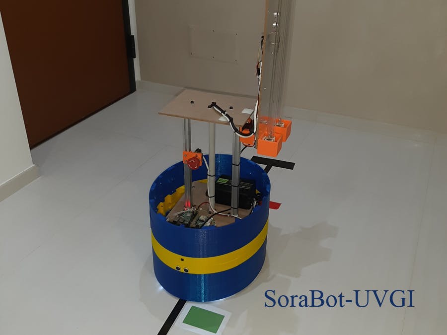
First of all I gave it a name: SoraBot-UVGI.
I thought of making a robot that could be manufactured by as many people/companies as possible, so the cost of construction was a fundamental element. To keep the cost low I had to exclude all those sensors and components that would have made it rise. So, I immediately ruled out the use of cameras, Lidars, etc... and I thought of a solution based on a very low cost line sensor: a robot that would be able to follow a simple black (or white) tape drawn along the way. An optimized path along the perimeter of the surfaces to be sanitized would have allowed me to maximize the use of the battery and UVC lamps (the lamps have a certain number of operating hours and ignitions, beyond which they no longer work).
For the motors, I found a cheap kit solution: it costs only $62.5.
For the batteries, I used a 12V 7Ah lead acid battery in the tests, but more batteries could be inserted to increase the robot autonomy or it is also possible to use other types of batteries, such as LiPo.
In general, the number of batteries depends on the length of the path (read more in the Power Supply section) and how much surface needs to be sanitized (read more in the UVC Lamp Section).
I thought of using ROS (Robot Operating System) to control the robot. Linux Operating System is required. So I installed ROS on a Raspberry Pi 3, that is very cheap. Furthermore, ROS simplifies the expandability of the robot: for example, if another team wants to add a Lidar, they can do it and integrate it without changing the entire robot's software and hardware.
I made SoraBot-UVGI autonomous: this way it could be used at any time and work even during closing hours, when there are no people. In any case, if there are people around, SoraBot-UVGI is equipped with two SS-430L-BK sensors that detect the presence of people through IRs. When one or more people enter the SoraBot-UVGI field of action, the robot stops, immediately turns off all UVC lamps and emits an audible alarm signal (beep beep beep).
Each company has a different building plan, that’s why I decided to create a line follower. With black tape on a light surface (or white on a dark surface), I created the path to follow inside the rooms and I marked with different colors the points to be sanitized (such as door handles). I equipped SoraBot-UVGI with two color sensors to identify these points. When the robot detects a line of a certain color (next to the black line), it performs additional operations: it can stop for some seconds or minutes, extend the UVC lamps to illuminate the surface of a table, while continuing the movement; it can approach a toilet and extend the lamps horizontally to sterilize its entire surface. I inserted two ultrasonic sensors (one at the front and one at the rear), so that, in the presence of obstacles, the robot stops (it is easy to implement a software system to circumvent any obstacles).
An important consideration concerns the UV-C dose required to inactivate the virus. It is evident that with the same UV-C power the distance will strongly affect the virus inactivation time. In the case of a table (horizontal surface), if the lamp is vertical, there will be an inactivation gradient: at the edge the required UV-C dose will be lower than in the center or at the opposite end. This problem does not arise for Sorabot-UVGI, because the lamps can be tilted and made parallel to the surface to be sanitized. This allows a consequent reduction in exposure times, a reduction in the overall execution time of the robot, reducing the battery consumption and increasing the surface sanitized with respect to the life of the UV-C lamps.
Sorabot-UVGI is equipped with a modular UV-C lamps system consisting of two 12W-UVC (36W) lamps capable of tilting. The module has a UV power at one meter of 191.08uW/cm2. By increasing the number of modules, the UV power is increased and the time to reach the required UV DOSE is reduced.
Functionality
- SoraBot-UVGI works through autonomous navigation (when UV irradiation is being performed, the robot is fully autonomous); if needed it is extremely simple to implement a remote control. SoraBot-UVGI is equipped with sensors to detect people along the way: in this case the system deactivate the UV-C lamps, harmful to humans; furthermore it is provided with ultrasonic sensors to identify obstacles along the way;
- The type of UV-C lamps used are ozone free and when people are detected the UV-C lamps are instantly turned off, in order to remain under the TLV;
- SoraBot-UVGI is equipped with two motorized wheels plus a caster wheel and can rotate 360 degrees;
- The switching on and switching off times of the lamps are saved in a file, in order to have the number of ignitions and the time of use of the UV-C lamps. SoraBot stores the sequence of stops at the UVGI points and checks the emission of UV-C rays through an ultraviolet sensor. The UV sensor and the time of use will tell you when you need to change the UV-C lamps;
- SoraBot-UVGI is modular: different levels of batteries can be added and the robot consumption is extremely low. The recharging time depends on the type of batteries used and on the robot consumption (for example, about three hours for LiPo batteries). The batteries can be placed on a higher level than the motors, so they can be easily swapped out;
- Normally the UV-C lamps are within the perimeter of SoraBot. When they are tilted (in order to avoid collisions), they are equipped with an ultrasonic proximity sensor that blocks movement;
- SoraBot-UVGI is small and designed to move around in standard bathrooms (it also goes in reverse gear), its dimensions are 1, 2ftx1, 46ft WxL, variable height (test robot H:2, 95ft);
- SoraBot-UVGI is durable. Obviously, some parts of the robot will wear out first, others very slowly. The critical parts are certainly the motors and batteries.The motors can be changed very easily, just unscrew a few bolts. The batteries, placed in their level, become easily swapped out when depleted. In general, to understand which are the critical parts, the robot must be used for many hours.Also, some parts, like LM2596 modules (read more in the power supply section) can be replaced with automotive or industrial grade parts.
- SoraBot-UVGI is designed to perform a precision sanitization. The robot follows a path drawn with a line and identifies colored markers along its way, indicating the UVGI points and some other additional functions; this way it can approach and sanitize vertical surfaces (such as handles), and also horizontal surfaces (such as tables, chairs and toilets) by tilting the lamps. Thus, SoraBot-UVGI can even get close to 1ft from the surface. If I use only two 12W-UV-C lamps at a distance of 1ft, the dose of 25mJ/cm^2 is delivered in about 12 seconds; if I use two 12W-UV-C lamps at a distance of 6ft, the dose of 25mJ/cm^2 is delivered in about 7 minutes and 18 seconds. SoraBot-UVGI is modular, so you can add other lamps to halve the exposure times: if I use four 12W-UV-C lamps at a distance of 6ft, the dose of 25mJ/cm^2 is delivered in about 3 minutes and 39 seconds.
Manufacturability
- SoraBot-UVGI is quickly manufactured: it has been designed using readily available components, that can be also easily replaced with equivalents;
- SoraBot-UVGI is economical and components costs are listed in the Bill of Materials (see above);
- All plastic parts were printed on a $200 3D printer with around 2kg of PLA;
- The Bill of Materials (BOM) is less than 1000 USD;
- I have documented everything with images and section BOM, in order to make the production process as simple as possible;
- All building materials (including the required software) are readily available in quantity for mass production.
ROS (Robot Operating System)
https://www.ros.org/about-ros/
"The Robot Operating System (ROS) is a flexible framework for writing robot software. It is a collection of tools, libraries, and conventions that aim to simplify the task of creating complex and robust robot behavior across a wide variety of robotic platforms.
Why? Because creating truly robust, general-purpose robot software is hard. From the robot's perspective, problems that seem trivial to humans often vary wildly between instances of tasks and environments. Dealing with these variations is so hard that no single individual, laboratory, or institution can hope to do it on their own.
As a result, ROS was built from the ground up to encourage collaborative robotics software development. For example, one laboratory might have experts in mapping indoor environments, and could contribute a world-class system for producing maps. Another group might have experts at using maps to navigate, and yet another group might have discovered a computer vision approach that works well for recognizing small objects in clutter. ROS was designed specifically for groups like these to collaborate and build upon each other's work, as is described throughout this site."
I have created several ROS nodes in Python and C/C++ illustrated in the sections below. I also created two more ROS nodes:
- the ROS node that saves in a file the switching on and switching off times of the lamps;
- the ROS node that drives the robot;
ROS node - Record UV-C use data
I have created a ROS node in Python that saves in a file the switching on and switching off times of the lamps. The node is called "savedata" and subscribes a ROS Topic "uvcontrol". The name of the file is "switchlamps.txt" and the ROS node appends data.
I have attached the source code of the ROS node.
ROS node - Robot Guide
I have created a ROS node in Python that drives the robot. The node is called "guide".
The ROS Topics subscribed are:
- "linefollower";
- "ultrasonic";
- "kemet";
- "colors";
- "uvcvalue".
The ROS Topics published are:
- "drivers";
- "uvcontrol".
For questions of time (Submissions closing) I have made only the basic functionalities to demonstrate the functioning of the robot.
I have attached the source code of the ROS node.
Motors SectionThe robot is equipped with two motors and a rear caster wheel.
For the motors I have used a "Power Window Motors w/ 5" Wheels (Pair)" sold by Cytron.
Assembling Motors
You need:
- Cytron Technologies Cytron Power Window Motors w/ 5" Wheels (Pair);
- 3D printing of support for left motor: "SoraBot-UVGI | left motor support";
- 3D printing of support for right motor: "SoraBot-UVGI | right motor support";
- Four machine screws, M5x20;
- Eight machine screws, M6x20;
- Wires, heat-shrink tubing and female crimp terminals.
Motors Drivers
To control the motors I have used two MD20A - 20Amp 6V-30V DC Motor Drivers.
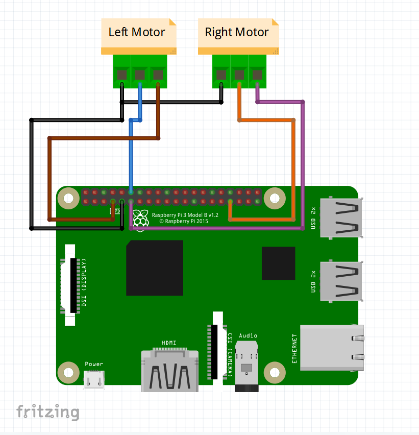
Connection of two drivers to Raspberry Pi 3
I control the drivers directly from the Raspberry Pi 3.
- The GND pins of drivers are connected to the GND pin (pin 9) of the Raspberry Pi 3;
- The PWM pin of left driver is connected to the GPIO18 of the Raspberry Pi 3;
- The PWM pin of right driver is connected to the GPIO13 of the Raspberry Pi 3;
- The DIR pin of left driver is connected to the GPIO4 of the Raspberry Pi 3;
- The DIR pin of right driver is connected to the GPIO17 of the Raspberry Pi 3.
I have created a ROS node in Python that controls the drivers through the GPIO of Raspberry Pi 3. The node is called "drivers" and subscribes a ROS Topic "drivers". The Topic data structure is:
drivers_msg.msg
uint64 inc
uint8 direction
uint8 velocity
uint8 rotation
Note:
- direction: 0 forward | 1 backwards;
- velocity: 0-100;
- rotation: 1 turn left | 2 go straight ahead | 3 turn right;
I have attached the source code of the drivers ROS node.
Assembling MD20A
You need:
- Two Cytron Technologies MD20A - 20Amp 6V-30V DC Motor Drivers;
- Eight machine screws, M3x10;
- Wires, heat-shrink tubing and female crimp terminals.
For the tests I have powered the robot with a 12V 7Ah lead acid battery.
The autonomy depends on how many UV-C lamps are on and how long the path to follow is.For example, to increase autonomy, it is possible to replace the lead-acid battery with one or more 20Ah LiPo batteries or similar. With the same capacity, LiPo batteries are lighter and smaller, so they can be used longer.
If you want to increase the number of lead batteries you can insert two batteries in the first level (see the following image).
If that is not enough, you can insert a new level made up only of batteries. SoraBot is designed to be able to insert many levels.
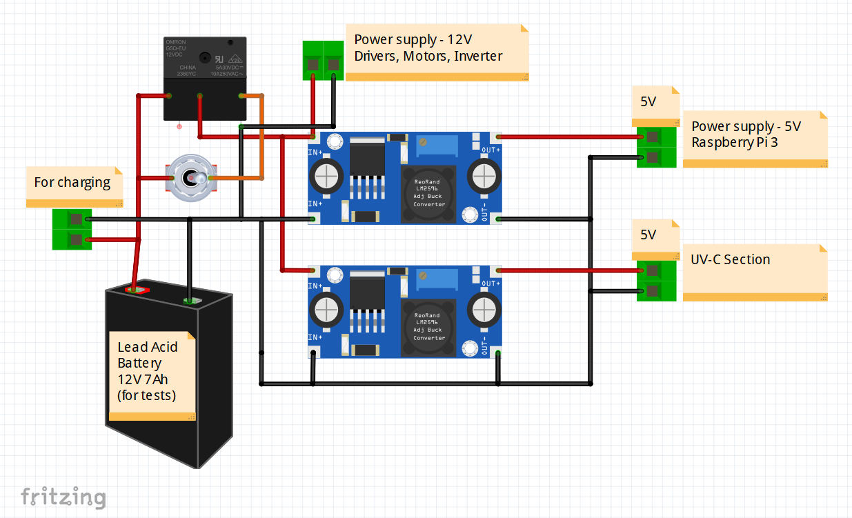
Electrical schematic
I have used two LM2596 modules to supply the 5V to the robot with a current greater than 5A (industrial grade DC-DC Converter: DDR-30G-5).
To adjust the output of the LM2596 module and obtain 5V, you need to use the blue trimmer.
Instead of a switch I have used an emergency button and apower relay.
Assembling
You need:
- 12V 7Ah lead acid battery;
- Emergency button;
- Coil 12V | Contact 30A - T92P7D22-12 - Power relay;
- Two LM2596 modules;
- Two 5A diodes;
- Connector for charging;
- Wires, heat-shrink tubing, female jumpers for wire and mammut clamps, etc...
The MH Sensor Module mounts a TCRT5000L Reflective Optical Sensor with Transistor Output. The TCRT5000 and TCRT5000L are reflective sensors which include an infrared emitter and a phototransistor in a leaded package which blocks visible light. The package includes two mounting clips. TCRT5000L is the long lead version.
Features
- Supply voltage: 3.3 - 5V;
- Test reflection distance: 1mm to 25mm;
- Output: digital switch output (0 and 1);
- The module has a precision potentiometer to adjust threshold for D0 output.
Modulepinout
- VCC: Power supply;
- GND: Ground, connect it to the negative pole;
- D0: digital switch output (0 and 1);
- A0: Analog output.
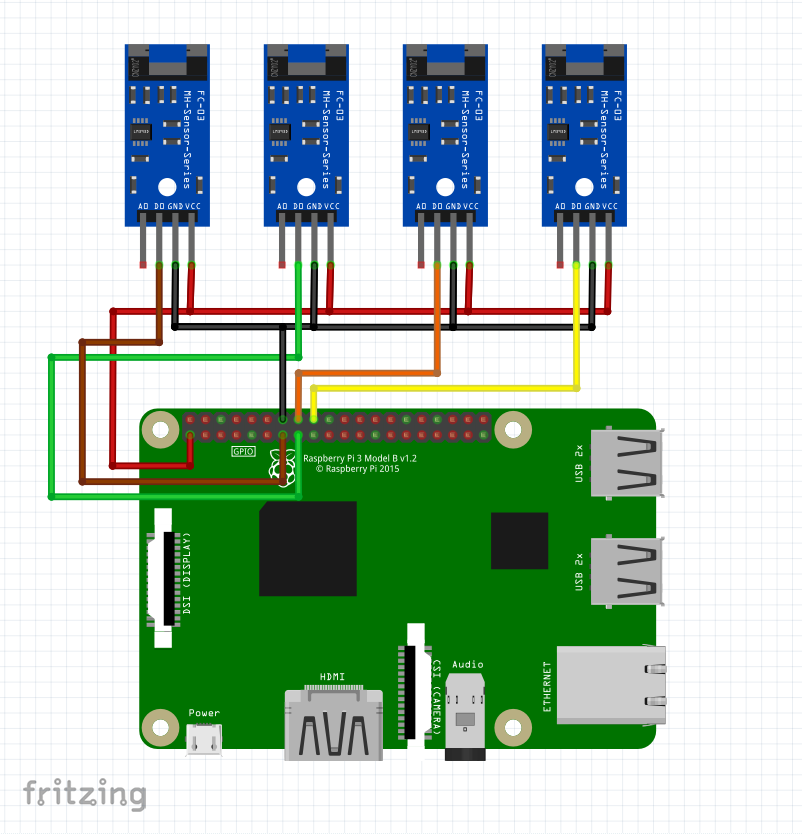
Connection of four MH Sensor Modules to Raspberry Pi 3
I have connected four MH sensor modules to Raspberry Pi 3 in order to read the output value.
- The VCC pins of MH sensor modules are connected to the 3.3V pin of the Raspberry Pi 3;
- The GND pins of MH sensor modules are connected to the GND pin of the Raspberry Pi 3;
- The D0 pin of the first MH sensor module is connected to the GPIO27 pin of the Raspberry Pi 3;
- The D0 pin of the second MH sensor module is connected to the GPIO22 pin of the Raspberry Pi 3;
- The D0 pin of the third MH sensor module is connected to the GPIO23 pin of the Raspberry Pi 3;
- The D0 pin of the fourth MH sensor module is connected to the GPIO24 pin of the Raspberry Pi 3.
I have created a ROS node in Python that reads digital switch outputs of four MH sensor modules through the GPIO of Raspberry Pi 3 and publishes them on ROS Topic. The node is called "linefollower" and the data rate is 10Hz. The Topic name is "linefollower" and its data structure is:
linefollower_msg.msg
uint64 inc
uint8 followerSX
uint8 followerSXC
uint8 followerDXC
uint8 followerDX
Note. SX = Left; SXC = Left-Center; DX = Right; DXC = Right-Center.
The type of data published on the topic are all unsigned int 8 and the values are zero (0x00) for the black line that is not present or one (0x01) for the black line that is present.
I have attached the source code of the linefollower ROS node.
Assembling
You need:
- Four line Followers (MH Sensor Module with TCRT5000L);
- 3D printing of "SoraBot-UVGI | line follower sensors support";
- Two machine screws, M3x20;
- Four nylon machine screws, M3x10;
- Wires, heat-shrink tubing, female jumpers for wire and mammut clamps.
This module is based on the TCS3200 chip which is a programmable color light-to-frequency converter.
Features
- Supply voltage: 2.7 - 5.5V;
- Programmable color light-to-frequency converter;
- Output frequency scaling;
- Four LEDs to illuminate the surface.
Modulepinout
- VCC: Power supply;
- GND: Ground, connect it to the negative pole;
- S0: frequency scaling selection input (internal pull-up);
- S1: frequency scaling selection input (internal pull-up);
- S2: Photodiode type selection input;
- S3: Photodiode type selection input;
- OUT: Output frequency (fo);
- LED: white LEDs control.
- 100% → fo = 600kHz
- 20% → fo = 120kHz
- 2% → fo = 12kHz
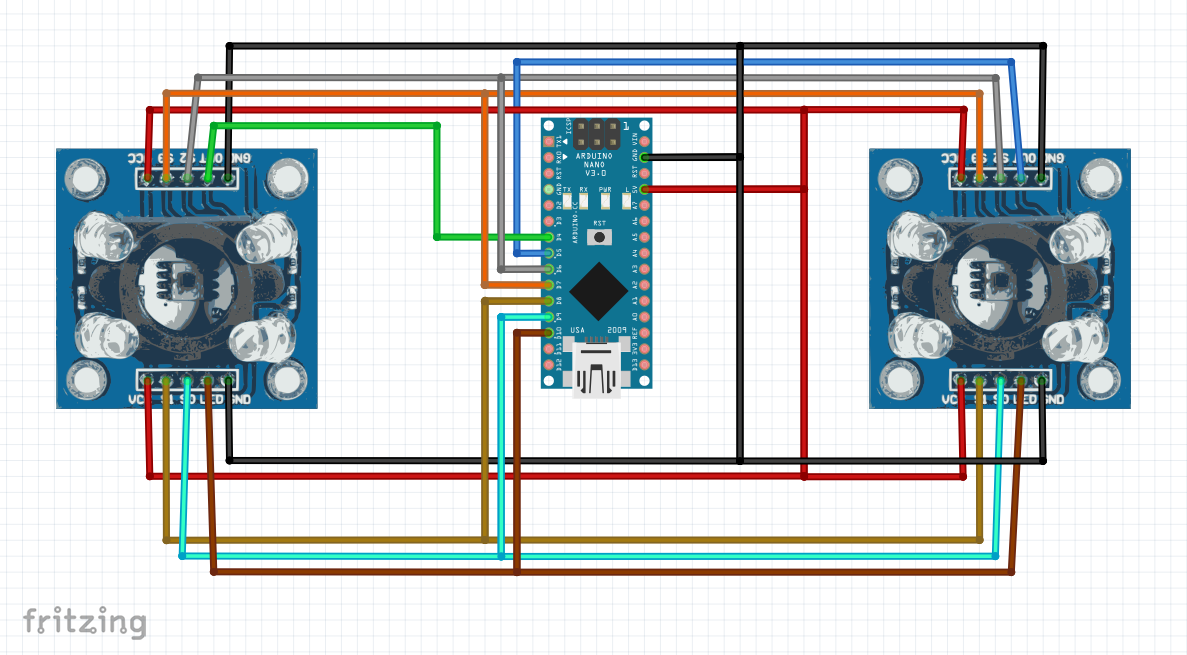
Connection of twoGY-31sensormodules to Arduino Nano
I have used an Arduino Nano in order to read and control two GY-31 modules.
- The VCC pins of GY-31 modules are connected to the 5V pin of Arduino Nano;
- The GND pins of GY-31 modules are connected to the GND pin of Arduino Nano;
- The S0 pins of GY-31 modules are connected to the D9 pin of Arduino Nano;
- The S1 pins of GY-31 modules are connected to the D8 pin of Arduino Nano;
- The S2 pins of GY-31 modules are connected to the D6 pin of Arduino Nano;
- The S3 pins of GY-31 modules are connected to the D7 pin of Arduino Nano;
- The OUT pin of GY-31 module (left) is connected to the D4 pin of Arduino Nano;
- The OUT pin of GY-31 module (right) is connected to the D5 pin of Arduino Nano;
- The LED pins of GY-31 modules are connected to the D10 pin of Arduino Nano.
The Arduino Nano is equipped with a USB. I will use the USB to send an ASCII string with the state of the sensors to the Raspberry Pi 3. The string consists of 18 ASCII characters:
SX;r;g;b;DX;r;g;b\r\n
SX: Start string of value of left color sensor;
DX: Start string of value of right color sensor;
r: red value;
g: green value;
b: blue value;
\r\n: Carriage return and new line | End of string.
The string will be sent with an interval of about 100ms.
Serial port settings:
- Baud rate: 9600;
- Data bits: 8;
- Parity: None;
- Stop bits: 1;
- Flow control: None.
I have created a ROS node in Python that reads data sent from Arduino Nano through the USB serial port and publishes them on the ROS Topic. The node is called "colors" and the data rate is 10Hz. The Topic name is "colors" and its data structure is:
colors_msg.msg
uint64 inc
uint8 SX_Red
uint8 SX_Green
uint8 SX_Blue
uint8 DX_Red
uint8 DX_Green
uint8 DX_Blue
Note. SX = Left; DX = Right.
The type of data published on the topic are all unsigned int 8 and the values are zero (0x00) for the color that is not present or one (0x01) for the color that is present.
I have attached the source code of the colors ROS node and Arduino Sketch.
Assembling
You need:
- Two color sensors - GY-31 module;
- Arduino Nano;
- USB Cable 0.5m (USB-A / miniUSB-B);
- Two 3D printings of "SoraBot-UVGI | color sensor support";
- Two machine screws, M3x20;
- Twelve machine screws, M3x6;
- Four Hex Stand-Offs, M3x10;
- Wires, heat-shrink tubing and female jumpers for wire.
The HC-SR04 ultrasonic distance sensor is an economical sensor that provides from 2cm to 400cm of non-contact measurement functionality with a ranging accuracy that can reach up to 3mm.
Features
- Supply voltage: 5V;
- Ranging distance: from 0.02m to 4m;
- Measure angle: 15°;
- Working frequency: 40kHz.
Modulepinout
- VCC: Power supply;
- GND: Ground, connect it to the negative pole;
- Trig: Pulse Input (apply at least 10us high level signal in order to start the measurement of distance);
- Echo: Pulse Output (to calculate the distance, measure the pulse width: pulseWidth).
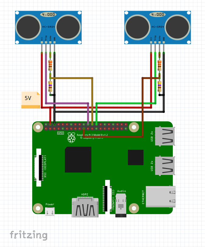
Connection of two HC-SR04 ultrasonic distance sensors to Raspberry Pi 3
I have connected two HC-SR04 ultrasonic distance sensors to Raspberry Pi 3 in order to verify the absence of obstacles in front and back the robot.
- The VCC pins of HC-SR04 ultrasonic distance sensors are connected to the 5V pin of Raspberry Pi 3;
- The GND pins of HC-SR04 ultrasonic distance sensors are connected to the GND pin of Raspberry Pi 3;
- The Trig pin of HC-SR04 ultrasonic distance sensor (front) is connected to the GPIO25 pin of the Raspberry Pi 3;
- The Echo pin of HC-SR04 ultrasonic distance sensor (front) is connected through a voltage divider to the GPIO8 pin of the Raspberry Pi 3;
- The Trig pin of HC-SR04 ultrasonic distance sensor (back) is connected to the GPIO7 pin of the Raspberry Pi 3;
- The Echo pin of HC-SR04 ultrasonic distance sensor (back) is connected through a voltage divider to the GPIO10 pin of the Raspberry Pi 3.
I have created a ROS node in C++ that measures the distance of obstacles in front of and behind the robot. If an obstacle is less than 30cm from the robot, the presence of an obstacle is signaled on ROS Topic. The node is called "ultrasonic" and the data rate is 10Hz. The Topic name is "ultrasonic" and its data structure is:
ultrasonic_msg.msg
uint64 inc
uint8 ultrasonicF
uint8 ultrasonicB
Note. F = Front; B = Back.
The type of data published on the topic are all unsigned int 8 and the values are zero (0x00) for the obstacle that is not present or one (0x01) for the obstacle that is present.
The formula for calculating the distance is:
distance = (pulseWidth * velocity of sound) / 2
I have attached the source code of the ultrasonic ROS node.
Assembling
You need:
- Two ultrasonic distance sensors - HC-SR04;
- Two resistors of 330Ohm;
- Two resistors of 470Ohm;
- Wires, heat-shrink tubing and female jumpers for wire.
KEMET’s Pyroelectric Infrared Sensors (SS-430L-BK) are ideal for safety, because they detect human proximity using IR.
KEMET’s proprietary piezoelectric ceramic material and structural development of the pyroelectric infrared sensor enables human presence detection through solid plastic materials or glass, which allows more mechanical and optical appearance design possibilities of the end product. The sensor can be used without a lens or, to extend the detection range, a proprietary KEMET lens can be used in 3 different colors.
The K-board sensory system, in this application, is composed of two KEMET SS-430L-BK sensors, one front and the other back, in order to have a greater surveillance area and understand if people are present...read more about K-board
The K-board is equipped with a buzzer that emits an acoustic signal when one of the three sensors SS-430L-BK detects a person. Also there is a different colored LED for each sensor: it lights up when a person is detected.
The K-board sends the status of the three KEMET SS-430L-BK sensors every 100ms. When a person is detected in front of the sensor, a beep is emitted from the buzzer and the respective LED lights up. The LEDs are red, green, and yellow. Red refers to sensor 1, green refers to sensor 2 and yellow refers to sensor 3. The beep has a duration of approximately 200ms and three different tones. The LEDs turn on for about 500ms.The K-board is equipped with a USB. I will use the USB to send an ASCII string with the state of the sensors to the Raspberry Pi 3. The string consists of five ASCII characters:
Kxyz\r
K : Start of string;
x : Sensor 1 status | 0 = no human body | 1 = human body;
y : Sensor 2 status | 0 = no human body | 1 = human body;
z : Sensor 3 status | 0 = no human body | 1 = human body;
\r : Carriage return | End of string.
The string will be sent with an interval of about 100ms.
I have created a ROS node in Python that reads data sent by the K-board through the USB serial port and publishes them on ROS Topic. The node is called "kemet" and the data rate is 10Hz. The Topic name is "kemet" and its data structure is:
kemet_msg.msg
uint64 inc
uint8 kemetF
uint8 kemetB
Note. F = Front; B = Back.
The type of data published on the Topic is unsigned int 8 and the values are one (0x01) or zero (0x00). The value one (0x01) indicates the presence of one or more persons; the value zero (0x00) indicates absense of people. KemetF refers to sensor one of the K-board; kemetB refers to sensor three of the K-board.
I have attached the source code of the Kemet ROS node.
For more info read my project of K-board here.
I used the Seeed Fusion PCB Assembly Service for a new prototype and I was very satisfied. Seeed is fast and produce superior quality PCBs. Free DFA and free functional tests are also provided. Check out the website.
In this application I only use two sensors (sensor 1 and sensor 3).
Assembling
You need:
- Two KEMET’s Pyroelectric Infrared Sensors SS-430L-BK;
- K-board;
- USB Cable 0.15m (USB-A / microUSB-B);
- Wires, heat-shrink tubing and female jumpers for wire.
I have created a modular system in order to increase the UV-C power according to the surfaces that need to be sanitized.
The basic structure consists of two 36W Philips lamps, two 2G11 lamp holders and one ballast.
The power on/off control is made via an SSR that controls the high voltage of inverter (that raises and transforms the 12VDC into 220VAC).
The base module is equipped with a servo that allows it to tilt until it becomes horizontal.
In addition, the module is equipped with an ultrasonic proximity sensor and a UV sensor (this one verifies that the lamps are working).
UV Detection Sensor
ARD2-2062 is a sensor module used for detecting the intensity of incident ultraviolet (UV) radiation. This module is based on the sensor UVM-30A, which has a wide spectral range of 200nm–370nm. The module outputs an electrical signal, which varies with the UV intensity.
ARD2-2062 sensormodule pinout
- - → GND (Ground), connect it to the negative pole;
- out → Analog output;
- + → VCC, power supply (3.0 ÷ 5.0VDC).
Hardware and Firmware
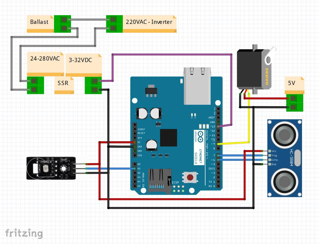
To control a UV-C module I have used an Arduino Uno.
In the following figure you can see the electrical connection of module hardware.
In the following figure you can see the flow chart of the Arduino Uno sketch.
I have created a ROS node in Python that reads UV sensor data and publishes on ROS Topic. The node is called "uvcmodule" and the data rate is 10Hz. The Topic name is "uvcvalue" and its values are one (0x01) or zero (0x00). The value one (0x01) indicates the presence of UV-C; the value zero (0x00) indicates the absense of UV-C. In addition, the ROS node also sends the tilt and ON/OFF commands to the UV-C module. The node subscribes a ROS Topic "uvcontrol". The Topic data structure is:
uvcontrol_msg.msg
uint64 inc
uint8 on
uint8 horizontal
on: 1 (lamps ON); 0 (lamps OFF);
horizontal: 1 (lamps horizontal); 0 (lamps vertical).
I have attached the source code of the colors ROS node and Arduino Sketch.
Assembling
You need:
- Two 36W Philips lamps - 62878740;
- Two 2G11 lamp holders;
- 2x36W ballasts;
- ARD2-2062 UV Detection Sensor;
- Ultrasonic Distance Sensor HC-SR04;
- Arduino Uno;
- SSR;
- DS3225MG;
- Inverter 12VDC-220VADC 150W;
- 4x machine screws, M3x10;
- 2x machine screws, M3x20;
- 4x machine screws plus nut, M3x25;
- 4x machine screws, M4x35;
- Hot Glue Sticks;
- Wires, heat-shrink tubing and female jumpers for wire.
The assembly sequence can be seen in the following images.
If you have any questions or suggestions don't hesitate to leave a comment below. Thank you!






Comments
Please log in or sign up to comment.