


Hardware components | ||||||
_ztBMuBhMHo.jpg?auto=compress%2Cformat&w=48&h=48&fit=fill&bg=ffffff) |
| × | 1 | |||
 |
| × | 1 | |||
 |
| × | 1 | |||
| × | 1 | ||||
First of all we will build a street lighting system which will be powered by the combination of the ever-present but low-power RF energy with the strong but variable solar power input. Moreover, we will also show that the two Energy Harvesting systems together produced more usable electricity when combined into a hybrid system than when operating independently.
Our proposed LED DC Street Lights are better than the traditional AC Street light. These are environment-friendly and offer better efficiency, lower maintenance costs and prolonged lifetime
We design the system in three different scenarios of using Standalone, Hybrid and Complementary modes and compare the effectiveness of the systems. In Hybrid mode, the system will be able to harvest energy simultaneously from both the energy sources; whereas Complementary mode will be suitable for the condition that if the battery is almost fully charged, the system will automatically switch over to its alternate source of supply depending on a fixed threshold. This will help in sustaining the operation of the system and save the batteries from overcharging as well as complete discharge condition.
Next we are interfacing this system with Arduino which has bunch of sensors like motion sensor, humidity sensor, temperature sensor and ldr to control the smart turning on and off of the light.
We know about solar panels and solar energy harvesting. Let us learn about RF Energy Harvesting
General Overview of our proposed model
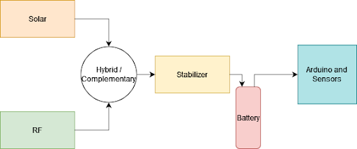
The system model for hybrid solar RF smart street light is illustrated below.
The proposed harvester is a hybrid solar/EM energy harvester that uses the solar antenna as well as harvests RF signals in the GSM 900 frequency band. The system is mainly composed of a 2.4 GHz custom dual-port antenna, an RF rectifier, a solar cell, a bq25504 Power Management Unity (PMU), a MSP430 Microcontroller (MCU), and a cc2500 transceiver. Here, the operation of the network is divided into four technology levels, i.e., sensing, computation, communication, and energy harvesting levels.
The SEH unit includes an Energy Source (i.e. Sun) and harvesting module (Solar Panel, MPPT and DC-DC Boost Converter). A SEH module consists of the following two main units: PV Cell, MPPT, Boost Converter.
The RF EH unit includes an Energy Source (i.e. nearby Base Stations) and harvesting module (Rectenna). The RF energy harvesting unit contains an antenna to collect RF energy and appropriate peripheral circuitry for electrical to DC conversion. An antenna, matching and rectifying circuits are the basic building blocks of a RF energy harvesting system.
The computation unit consists of a microcontroller used here i.e. arduino uno. The arduino was used for detecting and showing the sensor readings. This detection was possible by using the digital pins to connect to the sensors and then interpret it, and consequently showing us the data.
The communication unit consists of different sensors attached with the controller including motion sensor, humidity sensor, smoke sensor and an analog LDR which is connected as well with the load (street lamp) to control its brightness level according to the sun rays. The energy from the Sun is harvested by the solar module and converted to DC voltage. This can directly power the load or can be stored in a rechargeable battery for later use. A stabilizer is connected to control the unregulated voltage.The proposed harvester is a hybrid solar/EM energy harvester that uses the solar antenna as well as harvests RF signals in the GSM 900 frequency band. The system is mainly composed of a 2.4 GHz custom dual-port antenna, an RF rectifier, a solar cell, a bq25504 Power Management Unity (PMU), a MSP430 Microcontroller (MCU), and a cc2500 transceiver. Here, the operation of the network is divided into four technology levels, i.e., sensing, computation, communication, and energy harvesting levels.The SEH unit includes an Energy Source (i.e. Sun) and harvesting module (Solar Panel, MPPT and DC-DC Boost Converter). A SEH module consists of the following two main units: PV Cell, MPPT, Boost Converter.The RF EH unit includes an Energy Source (i.e. nearby Base Stations) and harvesting module (Rectenna). The RF energy harvesting unit contains an antenna to collect RF energy and appropriate peripheral circuitry for electrical to DC conversion. An antenna, matching and rectifying circuits are the basic building blocks of a RF energy harvesting system.The computation unit consists of a microcontroller used here i.e. arduino uno. The arduino was used for detecting and showing the sensor readings. This detection was possible by using the digital pins to connect to the sensors and then interpret it, and consequently showing us the data.
Case 1: Standalone SEH/RF EHHarvest energy even if only one source is available. All energy harvested is stored in a battery.
The system will be able to harvest energy simultaneously from both the energy sources. Here, the energy is collected from solar by means of solar panels and from EM source by means of a rectenna. Next is the DC combining circuit that combines the obtained DC outputs from both the harvesters to provide the necessary DC voltage and current.
The hybrid EH is far more power generating technique than the only standalone system, but usage wise the charging battery could only get charged up to a certain value and runs risks of overcharging as well as wasting of energy.
Even though it solves the problem of output efficiency by combining both the harvesters, application wise it still results in wastage of power.
The proposed system is designed in such a way that if the battery is closed to being charged fully, the system will automatically switch over to its alternate source of supply depending on a fixed threshold.
The complementary system is the one which is combines the better qualities of hybrid system and as well standalone system. This model at a given time generates just sufficient amount of energy by jumping between different modes as the situation demands thus avoiding overcharging.
Arduino and Sensor configurationThe sensors we are using are motion sensor, humidity sensor, smoke sensor and an analog LDR sensor.
Algorithm for Complementary energy harvestingNow the LDR will detect the intensity of the sunlight and whenever the intensity is below a certain threshold the solar energy harvesting will be turned off and only RF energy standalone system will be used.
Also the arduino will detect the battery voltage levels, if the battery is close to being fully charged solar harvesting will be turned off and only RF energy standalone system will be used.
For garden lighting setup, we have kept the humidity and the temperature sensor which will turn off the garden lights when it is raining or if there is a lot of smoke indicating a fire nearby.
Algorithm for turning smart light on and offNow the street lights will turn on automatically based on LDR reading when the light intensity reduces. Now when the street lights are on and the motion sensor detects no motion for a long time, the arduino can turn off the lights. The street lights will be again turned on as soon as motion sensor readings change. The arduino is in control of turning the light on and off based on sensor data.


Comments
Please log in or sign up to comment.