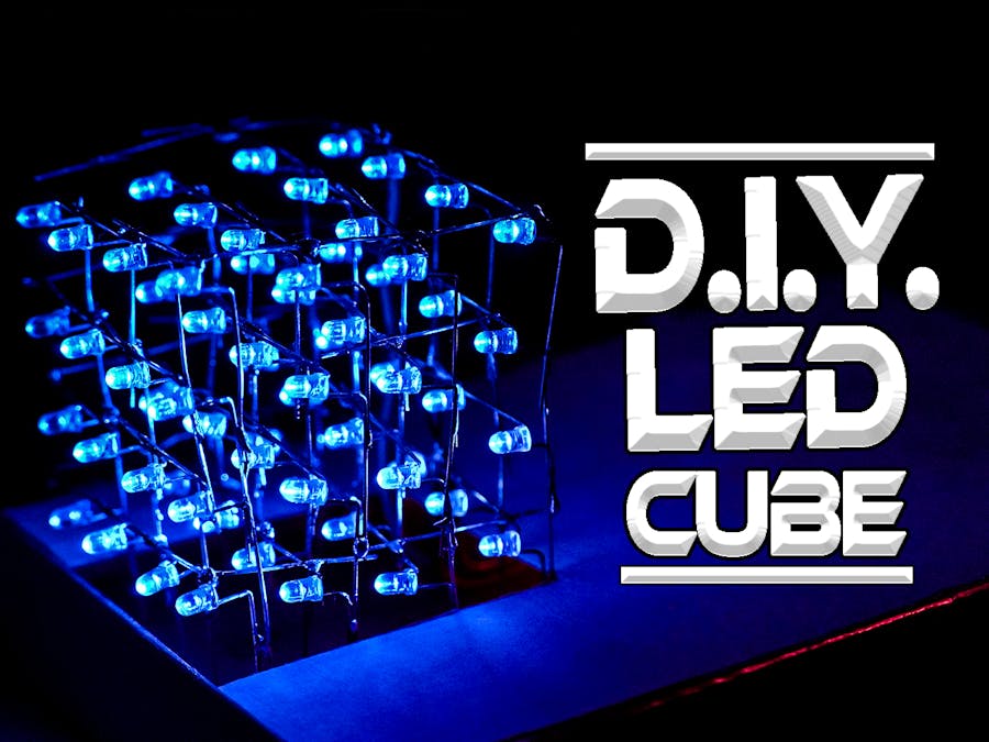
Hello there! recently, I was looking forward to change the decoration and theme of my desk, I wanted to add personal touch to my desk, which matched my channel theme too( which happens to be Electronics ;) ) Luckily I had lots of LEDs laying around from a previous project, Hence I decided to build a Mesmerizing LED CUBE using an Arduino Nano, so in this tutorial, we will learn how to Make this LED Cube in simple steps!
Supplies:1. Electronics
- Arduino Nano
- 64- 3mm blue LEDs
- Female Headers
- Rainbow Ribbon cable
- 4- 100Ω Resistor
- (OPTIONAL) general purpose prototype board
- PCB ( files attached in further steps).
2. Tools
- Soldering iron.
- Soldering wire.
- Soldering flux.(OPTIONAL).
- Scissors.
- Screw driver.
- Ruler scale.
- Hot Glue Gun (OPTIONAL)
- 3D printer (OPTIONAL)
- PCB Etcher (OPTIONAL)
3. Misc
- Cardboard.
- pencil.
- eraser.
Before we start making our LED cube and solder everything, it’s a good idea to test the LEDs, our LEDs operate at 3.3V, 20mA, we could easily test them using any 3.3v battery, in my case, I used a Lithium-Ion battery to test the LEDs.
Tips:
- the Longer lead is Positive and shorter one is Negative
- DON'T! reverse bias LED, you might damage it.
- DON'T use 5V power supply to test LED.
Once we are done with testing the led’s, we need to prepare a template on which the LED's can easily be soldered on and they retain uniformity, we can either use Cardboard, acrylic or directly 3D print the design of the template on a 3D printer, with the designs attached in this step! but unfortunately, we don't own a 3D printer, so we used a piece of cardboard to complete this step.
we took a 70 mm by 70 mm cardboard sheet. Since we are making a 4 x 4 x 4 LED cube, we will need 16 LEDs in a layer, so we will keep a separation distance of 15 mm between each LED, and complete the square.
you can directly take a printout of the template, and stick it on cardboard to use it for reference to plot holes ( please save paper don't be so lazy to draw few line :P )
Our LED is 3mm in diameter, so I will use a normal Philips head screwdriver which measures around 3mm in diameter to draw holes in this template, you can use a pencil or any pointed object to draw holes in this cardboard.
Tips:
- use Thick material of cardboard
- use 3D printed Template if possible.
- use drill-bit for accurate holes.
- don't apply too much pressure while using screwdriver for holes.
this is the most IMPORTANT step of this entire build! so carefully follow the instructions in this step!
- hold the LED with Positive lead that is the LONG lead on the left and short lead on the right side.
- Carefully fold the shorter lead toward you.
- Identify the Notch
- fold the longer lead towards left from the notch.
- adjust the Angle of leads, when viewed from top, it should make a 90 degree angle Once this is done,
- repeat for all 64 L.E.D's.
take the template that we made in Step3 and place the L.E.D.'s that we folded in Step4place them in template, with negative lead facing towards right and positive lead facing downwards, as show in picture.
this arrangement of 16 L.E.D's on this template is called one Column Layer. place the entire column and prepare it for soldering.
Step 6: Solder LED Column Layerif you are not very confident about soldering, check out this tutorials in which I cover the basics to soldering.
now that you are geared to solder, follow these steps to solder column layer.
- take the template from the last step.
- start soldering with Negative leads.
- complete one row at time.
- solder the positive leads.
- remove the Column from Template.
- Repeat this process for rest 3 Column Layers
Tips:
- use Flux for perfect solder joints.
- DON'T heat lead for more than 5 Seconds, you might damage the L.E.D.
- check for Dry Solder joints.
we made 4 individual column layers in last step, now its time to connect all the 4 column layers and complete this LED cube.
follow these steps to complete the LED Cube.
- place the template flat on your workbench.
- insert the positive lead pins from Column layer which we made in last step inside the Template.
- fold the negative leads of each layer towards you, with cube facing you.
- solder the negative layer pins.
- collect Leftover metal leads from other components or projects (if you don't have any, cut the leads of extra LEDS ).
- solder the Metal Leads to same layers, ensuring strength and proper power distribution.
Tips:
- DON'T short two layer's negative pins (i.e Layer1 should not be shorted with Layer 2, 3 or 4)
- make sure each positive Layer is connected with each layer.
- Add leads to Columns to add strength, but don't short negative of one layer with other while adding leads.
why this configuration?
the way this LED cube works is that we will command the positive of the required position along with required layer, to switch ON that LED, for example, if I want to switch ON the LED at position (1, 1, 1), I will connect the positive of power supply to (1, 1) and then I will ground the layer 1. so basically our circuit will activate 4 grounds and 16 Positive leads to create animations on LED cube. so we need to make a common ground from individual layers and common 16 Positive pins.
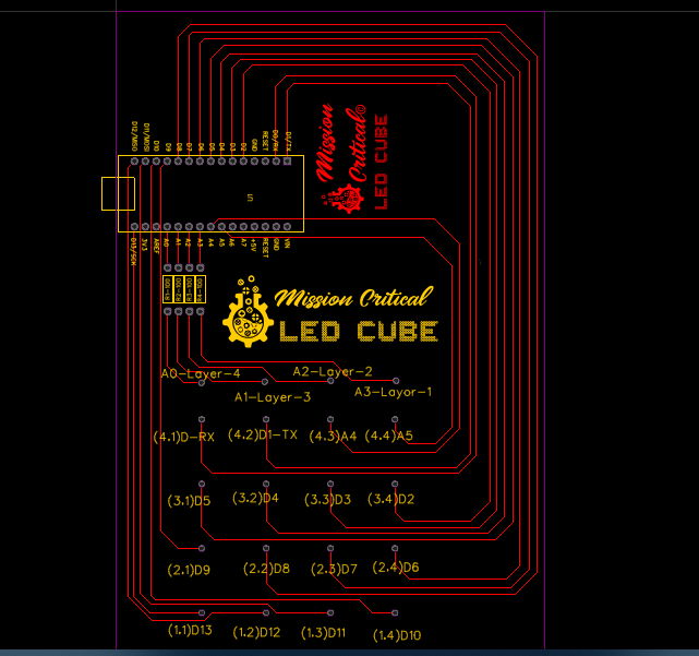
Step 8: Solder the PCBthis is quite a complicated circuit, if you are beginner, I would strongly recommend you to download the Gerber files and simply order the PCB from any PCB service and if you are experienced, or would like to try making this circuit on a General purpose board, follow these steps.
Steps:
- place the Arduino Nano with Female Headers on the pcb board.
- solder Female Headers on pcb board.
- solder LED cube on PCB.
- solder 4- 100Ω resistors at A3, A2, A1, A0 (i.e. Layer Pins).
- solder Column pins to cordinate locations using wire (1, 1)-D13 (1, 2)-D12 (1, 3)-D11 (1, 4)-D10 (2, 1)-D9 (2, 2)-D8 (2, 3)-D7 (2, 4)-D6 (3, 1)-D5 (3-2)-D4 (3-3)-D3 (3, 4)-D2 (4, 1)-D0 (4, 2)-D1 (4, 3)-A4 (4, 4)-A5, as shown in picture above.
- solder each layer pins to A3, A2, A1, A0 via Resistors using wire.
Tips:
- use solder flux.
- use solder fume extractor as exposing to solder fumes for long time is harmful.
- use flux for better solder joints.
- take your time and avoid short circuits.
- once you solder female headers on pcb, remove arduino and then perform soldering of remaining paths.
for arduino code, I modified the code from this post which was posted by forte1994, it was originally written on processing IDE software, which I converted and edited to make it work for my project, according to the pin-outs used for PCB design.
code is fairly simple, where in we create animation using binary data streams which forms patterns and we simply push that data on column and layer pins, I have provided proper commenting in required allocations, just in-case if you want to modify the code, if you like to understand the code, please download it and read it! also suggest any changes that might help optimize the code and make a better animation!
Step 10: Prepare the Enclosurethis is such a beautiful application, but this floating circuit deserves a Mesmerizing Box Enclosure too right? so I designed a box enclosure on the Autodesk's Fusion 360 CAD software which was build keeping in mind the P.C.B. dimension and other all other factors, you can download the 3D files of this enclosure box attached in this step or click here for grabcad link. I made this enclosure a 2 element box so that we can easily remove the circuit and fix any problems with arduino or circuit over time.
I made this enclosure design, but I don't have a 3D printer so I will settle down with a Cardboard replica of this same enclosure, with same dimensions, I have attached the 3D files, if you wish to make same enclosure with same dimensions, download the file and cut cardboard pieces according to the cad design and use a bit of hot glue to hold the pieces together, and we are good to go!
Tips:
- Be Careful while cutting the Cardboard.
- don't be ashame to ask for help from your parents if you are not comfortable handling scissors or blade.
- try to be Careful with Hot Glue gun, you might accidentally hot glue yourself
now we have completed all the steps and successfully built a LED Cube using Arduino Micro-Controller!
after this energetic build, its time to sit back and enjoy the mesmerizing result of our hard work!
Step 12: Connect With Us on Social Handles!Say hello to us or tag us if you make similar project. We would love to hear any suggestions/ideas, too!
Links:
Thank you!


Comments
Please log in or sign up to comment.