


Hardware components | ||||||
 |
| × | 1 | |||
_ztBMuBhMHo.jpg?auto=compress%2Cformat&w=48&h=48&fit=fill&bg=ffffff) |
| × | 1 | |||
 |
| × | 1 | |||
 |
| × | 1 | |||
Software apps and online services | ||||||
 |
| |||||
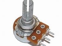
The potentiometer is a type of three-terminal variable resistance.
He's composed of a resistant disk where a cursor is moving.
As there are 3 terminals, one of them is connected to the cursor and others to the extremity of the resistant disk.
This system is used to collect a voltage that depends on the position of the cursor and the voltage at which the resistance is subjected.
Potentiometers are EVERYWHERE ( like electronic nowadays ) but particular in particular in the joystick.
And I don't know what else to say about potentiometers.
In this project we will be able to control the blinking of a LED and a servo motor.
Connections ( to control a LED ) :Arduino --> potentiometer ( based on the picture above ) :
5V --> 5V
AO --> Signal
GND --> GND
Pin 13 --> 1st extremity of the resistance
2nd extremity of resistance --> positive pin of LED
Negative pin of LED --> GND
Connections ( to control a servo motor ) :Arduino --> potentiometer
5V --> 5V
A0 --> Signal
GND --> GND
Arduino --> Servo
Red wire --> 5V
Brown wire --> GND
Yellow wire --> Pin 9
But you can use a potentiometer with a LED without code.You just have to make connections.
Arduino --> Potentiometer
3,3V --> 5V
GND --> GND
GND --> LED cathode
Potentiometer --> LED
Signal --> LED anode


Comments
Please log in or sign up to comment.