:Author: NewMC
:Email: {AuthorEmail}
:Date: Dec 17, 2018
:Revision: 0.1.0.0
:License: Public Domain
= Project: Water Level MonitorThis project will demonstrate how to build a water level monitor using an Arduino Nano, a Solu SL067 water level sensor, and an LED indicator. There are many possible uses for this simple system, examples include monitoring a sump pit (to control pump activation), rainfall detection, leakage detection, or monitoring plant water levels. I built this specifically to monitor the water level of my Christmas tree.
Credit:I initially found a similar project here.
I have significantly modified the code from the link above to use one LED with blink codes rather than the three LEDs that were used in the original development. I've also cleaned up the calibration instructions to hopefully make this completely understandable for a layman. You can simply assemble the circuit, upload my sketch to your Arduino, and follow the calibration requirements to have a functional and reliable water level monitor. Minimal programming knowledge is needed to modify my sketch to suit your needs.
**NOTE - I have only been using this for a few days, and do not know how well the sensor will hold up. There is potential for corrosion, and it's possible that a piece of debris (wet pine needle) could short two traces and give a false reading. I strongly recommend that you visually confirm your water level until you are confident that the sensor will continue to work as desired. I will continue to verify sensor operation every few days, but this helps to avoid the necessity to move gifts and tree skirt every day to check the water level.
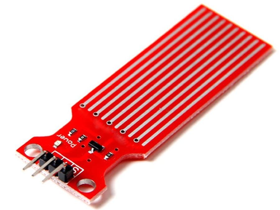
About the sensor:Sensor used for my development.
The sensor works by using a series of five exposed traces which are connected to system ground. Interlaced between every two ground trace is a sense trace, five ground traces and five sense traces in total. The sense traces are connected to a 1 Megaohm pull-up resistor. The sense traces are pulled high until a drop or plane of water shorts the sense trace to ground. This sensor will theoretically output an analog signal between 0-1024, but with the length of traces on this PCB I found a usable range between 480 and ~710. The sensor is not designed to be fully submersed, be mindful to install it so that only the exposed traces on the PCB will be exposed to contact with water. Output voltage of the sensor is 0 - 4.2 V, so this could be used as a digital input if only low/high indication is required.
The analog output values correspond to the following distance from bottom of the sensor (approximate):
480 = 0 mm
530 = 5 mm
615 = 10 mm
660 = 15 mm
680 = 20 mm
690 = 25 mm
700 = 30 mm
705 = 35 mm
710 = 40 mm
The sensor resolution decreases as the the water level increases.
== Installation1. Upload the sketch to your Arduino.
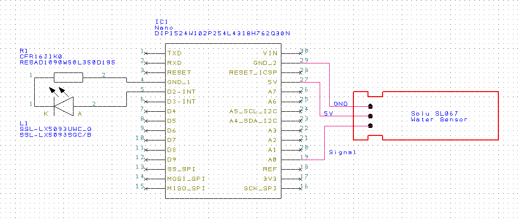
2. Assemble the circuit using the schematic included with this project.
**LED: The LED resistor must be installed between the circuit ground and LED. If your LED has one leg that is longer than the other, the longer leg needs to be connected to the supply voltage (D2 of Arduino).
*Note: I used ~2.5 ft wire length for the sensor and 2 ft wire length for the LED. This allowed me to place the Arduino away from the water, and route the LED to the end of a tree branch for visibility.
3. Follow the calibration instructions below (also included in the sketch):
**************************** Calibration/Setup ****************************
a) Connect Arduino to IDE and open serial monitor.
b) Insert depth sensor into water to a depth that you consider to be the minimum amount needed to trigger the full indicator. Note the value indicated in the serial monitor for use as the FULL level.
* Any value >= this will trigger the corresponding FULL blink code.
c) Repeat step 2 to determine the value you will assign to the LOW value.
* Any value above this but below the FULL value will trigger the corresponding INTERMEDIATE blink code.
* Any value below this value will trigger the corresponding LOW blink code.
d) Plug the values determined from steps 2 and 3 in as the const int FULL and LOW values in the sketch.
e) Upload the sketch with the updated values and your sensor is now calibrated.
4. Place your Arduino is some type of enclosure to prevent damage from water, moving parts, or shorts.
5. Install the system into your application.
=== Folder StructureWaterLevelMontior_SingleLED => Arduino sketch folder
├── WaterLevelMonitor_SingleLED.ino => main Arduino file
├── WaterLevelMonitor.png => an image of the required schematics
└── ReadMe.adoc => this file
=== LicenseThis project utilizes common electronic theory and C/C++ programming language. I am not claiming to hold a copyright or own any intellectual property related to the documents listed in the above section. This document, the associated Arduino sketch, and system schematic may be modified or distributed freely. This project is released under a Public Domain License.
=== DISCLAIMERThis SOFTWARE PRODUCT is provided by THE PROVIDER "as is" and "with all faults." THE PROVIDER makes no representations or warranties of any kind concerning the safety, suitability, lack of viruses, inaccuracies, typographical errors, or other harmful components of this SOFTWARE PRODUCT. There are inherent dangers in the use of any software, and you are solely responsible for determining whether this SOFTWARE PRODUCT is compatible with your equipment and other software installed on your equipment. You are also solely responsible for the protection of your equipment and backup of your data, and THE PROVIDER will not be liable for any damages you may suffer in connection with using, modifying, or distributing this SOFTWARE PRODUCT.
=== ContributingTo contribute to this project please contact NewMC
=== BOMID PART NAME PART NUMBER QTY
R1 1k 1/4 W Resistor TE Connectivity CFR16J1K0 (or similar) 1
L1 LED CREE C503B-RAN-CZ0C0AA2 (or similar) 1
S1 Solu Sensor Solu SL067 1
IC1 Arduino Nano A000005 1
PS Power Supply You choice, recommend 5 Vdc (>= 300mA) 1
=== HelpThis project contains the three files listed in the "Folder Structure" section above. These files provide a system schematic, basic instructions for implementation, and the software sketch needed to build the system. No further obligation of assistance is implied or given. For assistance, create a post at https://forum.arduino.cc/ and the community will offer guidance.


Comments
Please log in or sign up to comment.