


Hardware components | ||||||
 |
| × | 1 | |||
 |
| × | 1 | |||
 |
| × | 1 | |||
 |
| × | 1 | |||
 |
| × | 1 | |||
 |
| × | 5 | |||
 |
| × | 1 | |||
Software apps and online services | ||||||
 |
| |||||
 |
| |||||
Social distancing is one of COVID-19 's best means of escape. I strongly advise to staying at home. Even though we can not stop visits to certain homes by emergency. As we arrived in front of a house, we searched the doorbell button for the very first time. But the doorbell button can cause the disease to spread. If a certain infected person presses the button the virus remains on that button and when a non-infected person touches that button the virus spreads to that person. By using the touch-less doorbell we can avoid the risk.
Working Principle of Contact-less DoorbellVisitor has to place his palm nearer to the sensor. During this time sensor retrieves the latest value and compares it with the minimum proximity threshold limit. If it is less than the preset limit, SMS will be sent to the owner of the house, along with Buzzer notification. LED is used for the visitor that sensor has detected palm.
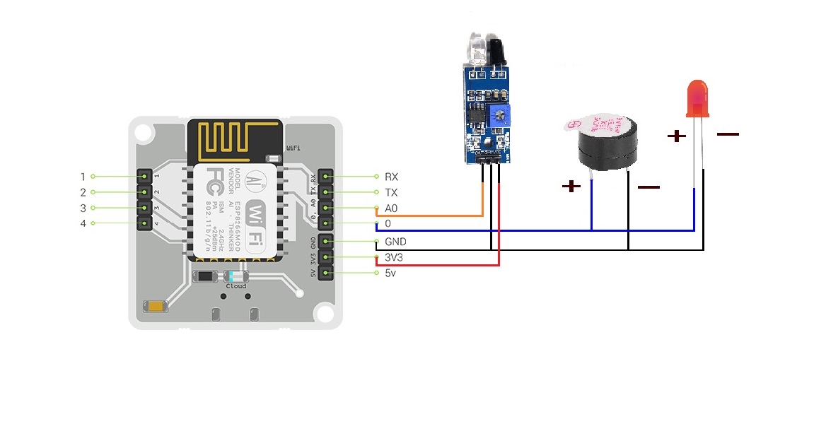
Hardware ConfigurationWARNING: Never power up the Bolt module while making the connections and ensure connections are proper before power up the module. Note that there is no wires touching 3v3 and GND.
Using Jumper Wires we will connect the WiFi Module pins to the breadboard. We can use five pins namely
- Power Supply Pins( 3v3, GND )
- Analog Pin ( A0 )
- Digital Pin ( 0 )
Steps for Connection
- Positive pin of Buzzer and LED should connect to pin number 0.
- Negative pin of Buzzer, LED as well as IR sensor should connect to GND pin.
- 3v3 to the VCC pin of the IR sensor.
- A0 to the OUT pin of IR sensor.
Component Description
IR Sensor
Mainly it consist of an IR LED, Photo diode, LM358 Op-Amp & a variable resistor.
Pin Configuration: There are three pins in this sensor module. VCC - Power supply input. GND - Power supply ground. OUT - Output pin.
Working :
IR LED transmit the light in the range of infrared frequency. Photodiode receiver will receive this transmitted light. It only takes place when an object/ light falls on it. The current flow is directly proportional to the amount of light falls on it. LM358 Op-Amp in voltage comparator mode. The comparator will compare the threshold voltage set using the variable resistor and the photodiode resistor voltage. Op-Amp output is connected to the 'OUT' pin.
Software ConfigurationWe will use Twilio for SMS notification and python3 for creating scripts.
Procedures for Twilio Account Setup
1. Open https://www.twilio.com/ In browser.
2. Click on sign up and start building.
3. Enter the required details.
4. You'll be asked to check your password, so go to your mailbox and check it out. Click on confirm mail.
5. Check your phone number. A code will be sent to your mobile phone. Please type the code in the cavity and submit it.
6. You see a page that says, "Do you write code? "Click on YES.
7. Then you'll be taken to a page with different programming language icons, Select PYTHON.
8. After that it displays a page that says, "What is your target today? "Choose" Twilio as a project.
9. Then it will take you to the page that says, "What do you want to do first? "Choose" Send or receive a message.
10. It will take you to the My First Twilio Project Dashboard page. You can edit your project as "My Project" in the bottom right corner.
11. Click on the button to get a trial number. You'll get your trial number. Please mention it somewhere and choose to select this number.
12. You could see the following details on your dashboard.
ACCOUNT SID and AUTH TOKEN.
13. You will be able to see 3 dots on the left side of the dashboard. Click it and add the SMS programmable file.


Comments
Please log in or sign up to comment.