Step 1: Arrange the components
Step 2: Insert the two 16 pin IC bases as shown in the image and solder it to the prototyping board.
Step 3: Insert and solder the 8 pin IC base to the prototyping board as shown in the image
Step 4:
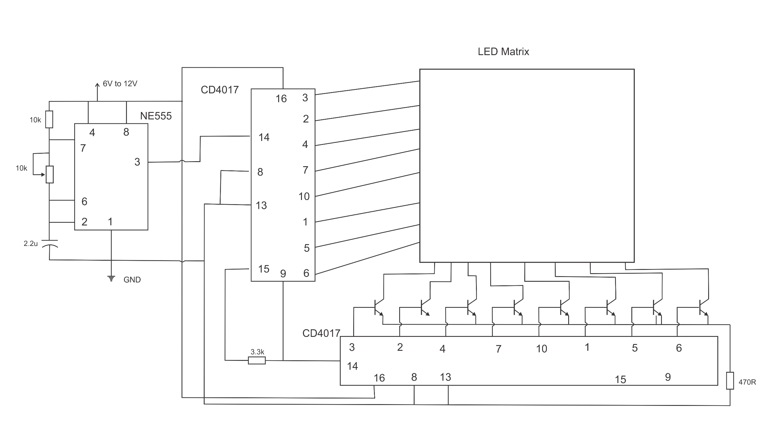
Insert and solder 10kΩ resistor, 3.3kΩ resistor, 10kΩ preset and 2.2µF capacitor as shown in the circuit diagram.
Step 5: Insert 3 ICs to their corresponding bases. Mind the correct pinout.
Step 6:
Solder ribbon wires to the outputs of the CD4017 ICs
Step 7:
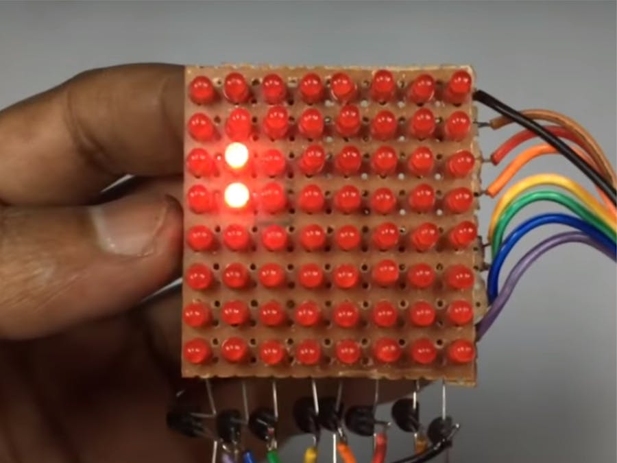
Connect collectors of the BC547 transistors in to corresponding negative pins of the LED matrix. Connect all the emitters of the BC547 transistors together
Step 8: Connect one output set from CD4017 to base pins of the BC547 transistors and other CD4017 IC’s outputs to positive pins of the LED matrix. Also connect the common emitters of the BC547 transistors to ground through a 470Ω resistor.
Step 9: Circuit is now ready. You can test it. You can change the speed of the running circuit by adjusting the preset.
When the circuit is powered NE555 will output a clock pulse according to the RC values of the capacitors and resistors. This pulse is then received by both CD4017 ICs causing to switching the outputs one after another. This is what we can see as a running LED effect. When the preset is adjusted the frequency of the clock pulse sent from the NE555 will change this will cause the speed of the running effect to change.
Sponsor Link: Utsource.net
Reviews: It is a trustworthy website for ordering electronic components to complete projects!
Conclusion:We can use these types of circuits for decoration and demonstrations purposes. Also this is a good project to a beginner in electronics field as NE555 and CD4017 are two of most versatile ICs in analog electronics.


Comments
Please log in or sign up to comment.