Watch the video first for a basic introduction and DEMO video-
INTRONow, if you're an electronic enthusiast or maker, you might know the Arduino platform very well. Generally, we start our Microcontroller journey with an Arduino Uno board and get introduced to Arduino IDE friendly MCUs which are based around 8-bit Atmel microcontroller ICs.
like UNO, nano, Leonardo, mega, DUE, etc
But that some point, your requirement hits that point where your code needs a much powerful MCU with some kind of connectivity, Bluetooth, or WIFI.
(for a low Price)
a normal Arduino is not powerful enough to drive for example a TFT Display with two motor drivers, a GPS with a Compass module altogether.
so what to do?
we can use a powerful arm chip or a board equipped with lots of sensors with an arm chip or we can just use an ESP8266 MCU which is a low-cost Wi-Fi microchip, with a full TCP/IP stack and microcontroller capability, produced by Espressif Systems.
ESP8266now let's take nodemcu as an example.
it's basically a breakout board for ESP12F which has AMS1117 setup fr 12V input and cp2102 chip for programming the MCU.
so practically we can make our own breakout circuit and use ESP12f in that instead of using ATMEGA minimal setup or Attiny.
Materials Required- ESP12F Module
- 10K Resistors x5
- Push Buttons x2
- LED x1
- breadboard or custom PCB
- Jumper wires
- FTDI Programmer
"PREPARING THE ESP12F"
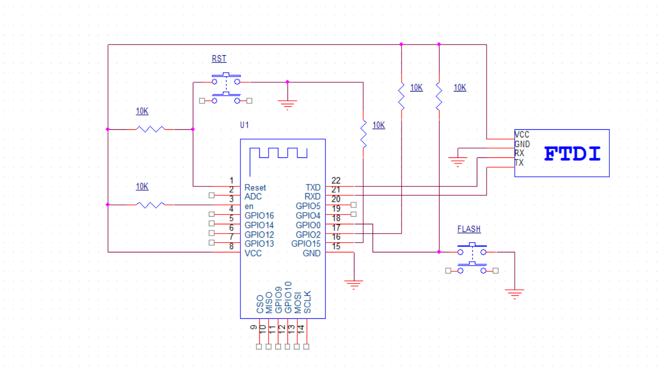
Wire the ESP12F on the Breadboard according to this scheme
But wait, ESP12F is not Breadboard compatible. so how to put it on a breadboard and flash it?
for that you gonna need a Breakout Board, if you don't have that then use a Perf Board with copper dots and silver copper wire.
watch the video -
"Flashing the ESP12F Module"
- Open Arduino IDE and install the ESP8266 boards. add- http://arduino.esp8266.com/stable/package_esp8266com_index.json into the additional board manager URL field.
- Open Board Manager from Tools>Board and FInd ESP8266 Platform (it's generally at the bottom of the list) install it!
- after installing it, close the Arduino IDE and reopen it, you will now see many ESP8266 Boards in Tools>Board
- now open Blink sketch and change the LED_BUILTIN to 2 (Blue onboard LED on esp12F)
- Hook the ESP12F setup (wiring is according to the scheme above) with your computer, in the tool menu, select the right board (ESP8266 Generic module) Upload speed- 115200, Flash Mode- DIO, Reset Method- CK and Flash Frequency - 40MHz.
- after selecting the right parameters, Hold the Flash Button connected to GPIO0 first and then Hold the RST button. then let go of them after 2 seconds and your board will enter the programming mode. do this before uploading your sketch.
- hit upload.
"RESULT"
ConclusionESP12F can now be implemented in any project with the Schematic given above and the programming process will remain the same with any sketch. just do follow the right Pinout/GPIO number.
what to do next?
Make a Breakout board or a PCB which have ESP12F as Main MCU, just remember to add Flashing and Reset Button for programming. or even go pro and add an auto-reset flash Transistor and use FTDI's DRT RST to trigger them.
Leave a comment if you run into some issue


_3u05Tpwasz.png?auto=compress%2Cformat&w=40&h=40&fit=fillmax&bg=fff&dpr=2)

Comments
Please log in or sign up to comment.