


Hardware components | ||||||
 |
| × | 2 | |||
 |
| × | 1 | |||
 |
| × | 1 | |||
 |
| × | 1 | |||
 |
| × | 1 | |||
 |
| × | 1 | |||
_ztBMuBhMHo.jpg?auto=compress%2Cformat&w=48&h=48&fit=fill&bg=ffffff) |
| × | 1 | |||
Software apps and online services | ||||||
 |
| |||||
Introduction
In this tutorial, we will explore the fundamental principles of capacitors and inductors by creating a simple circuit that demonstrates the continuous current flow of capacitors and the instantaneous change of inductor current. Using Light Emitting Diodes (LEDs) as visual indicators, we will see how these components behave under different electrical conditions. This project is perfect for beginners eager to understand basic electrical concepts in a practical setting
Materials Needed
Components:
- 1x LED (any color)
- 1x 220-ohm resistor
- 1x Capacitor (1000 µF)
- 1x Inductor (10 mH)
- 1x 555 timer IC (optional for pulse generation)
- 1x Breadboard
- Jumper wires
Tools:
Step-by-Step Instructions
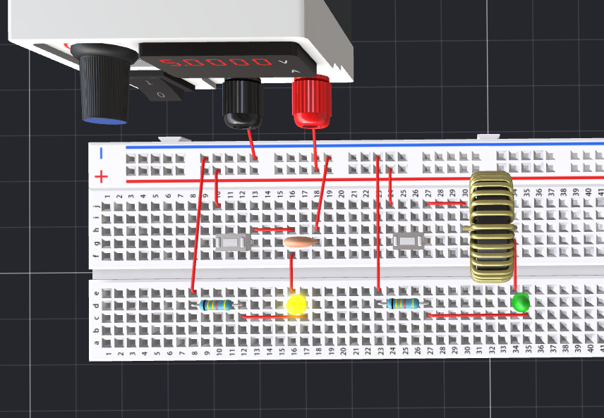
Circuit DesignBreadboard Layout: Start by placing the components on the breadboard. Here’s a simple layout:
- Connect the positive side of the capacitor to the power supply (+9V).
- Connect the negative side of the capacitor and the anode of the LED to the resistor (220 ohms).
- Connect the cathode of the LED to ground.
- Connect the inductor in series with the capacitor and LED setup.
- Breadboard Layout: Start by placing the components on the breadboard. Here’s a simple layout:Connect the positive side of the capacitor to the power supply (+9V).Connect the negative side of the capacitor and the anode of the LED to the resistor (220 ohms).Connect the cathode of the LED to ground.Connect the inductor in series with the capacitor and LED setup.
Conclusion
You’ve effectively created a circuit that illustrates the fundamental differences between capacitors and inductors. By observing how the LED reacts to changes in current, you’ve gained a better understanding of these critical components in electronic circuits. Experiment with different values of capacitors and inductors to see how they affect the LED operation, and feel free to reach out with any questions or further experiments you'd like to explore.
Join the PCBX community to simulate your own projects
https://www.pcbx.com/forum?mtm_campaign=E&mtm_kwd=hack
Register now to get your first Free PCB&PCBA coupon
https://www.pcbx.com/?mtm_campaign=E&mtm_kwd=BD
While the 3D simulation feature is still a work in progress, we would love to hear your suggestions and expectations. It's an open-source community; any sharing and feedback is welcome.
Your feedback will help our engineering team enhance the platform and better serve our users.


Comments
Please log in or sign up to comment.