


Hardware components | ||||||
 |
| × | 2 | |||
 |
| × | 1 | |||
 |
| × | 1 | |||
 |
| × | 1 | |||
Software apps and online services | ||||||
 |
| |||||
The push-pull follower comprises two complementary transistors that form a symmetrical output stage, alternating work at the output end to provide high current drive capability.
What is a Push-Pull Follower?A push-pull follower, also known as a class B amplifier, consists of two transistors—typically one NPN and one PNP. These transistors work together to amplify the input signal while maintaining a low output impedance. This configuration is particularly effective for driving loads that require significant current, such as speakers in audio applications.
Key Features:- High Current Drive: The alternating operation of the transistors allows the circuit to handle larger currents without overheating.
- Efficiency: The push-pull configuration minimizes power loss, making it more efficient than other amplifier types.
- Symmetrical Output: This design ensures that both halves of the input waveform are amplified, resulting in a more accurate reproduction of the signal.
To get started with simulating a push-pull follower, you can use PCBX Online Circuit Simulation.
Step 1: Create a New ProjectOpen the PCBX simulation workbench, and create a new project. Then you can start building your circuit.
Step 2: Add ComponentsFor a basic push-pull follower circuit, you’ll need the following components:
- Transistors: One NPN (e.g., 2N3904) and one PNP (e.g., 2N3906).
- Resistors: Two base resistors (typically around 10kΩ) to limit the base current.
- Load: A resistor or a speaker to represent the load.
- Power Supply: A DC voltage source (e.g., +12V and -12V).
- Transistor Configuration: Place the NPN and PNP transistors on the canvas. Connect the collector of the NPN to the load and the collector of the PNP to the positive voltage supply.
- Base Resistors: Connect the base of the NPN to the input signal through a resistor. Similarly, connect the base of the PNP to the input signal through another resistor.
- Emitter Connections: Connect the emitters of both transistors together and then to the ground.
- Load Connection: Connect the other end of the load to the ground.
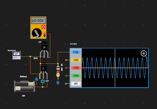
To observe the operation of the push-pull follower, you need to apply an input signal. You can use a function generator feature in your simulator to create a sine wave input.
Step 6: Run the SimulationOnce your circuit is set up, run the simulation. Observe the output waveform and compare it with the input signal. You should see that the output closely follows the input, demonstrating the push-pull follower’s ability to amplify the signal while providing a high current drive.
Simulating a push-pull follower circuit online is an excellent way to understand its operation and benefits. By following the steps outlined in this tutorial, you can gain hands-on experience with circuit design and analysis.
Feel free to experiment with different input signals and component values to see how they affect the circuit's performance. Happy simulating.
Join the PCBX community to simulate your own projects
https://www.pcbx.com/community?mtm_campaign=E&mtm_kwd=hack
Register now to get your first Free PCB&PCBA coupon
https://www.pcbx.com/?mtm_campaign=E&mtm_kwd=BD
While the 3D simulation feature is still a work in progress, we would love to hear your suggestions and expectations. It's an open-source community; any sharing and feedback is welcome.


_3u05Tpwasz.png?auto=compress%2Cformat&w=40&h=40&fit=fillmax&bg=fff&dpr=2)
Comments