


Hardware components | ||||||
 |
| × | 1 | |||
_ztBMuBhMHo.jpg?auto=compress%2Cformat&w=48&h=48&fit=fill&bg=ffffff) |
| × | 1 | |||
 |
| × | 1 | |||
 |
| × | 1 | |||
Software apps and online services | ||||||
 |
| |||||
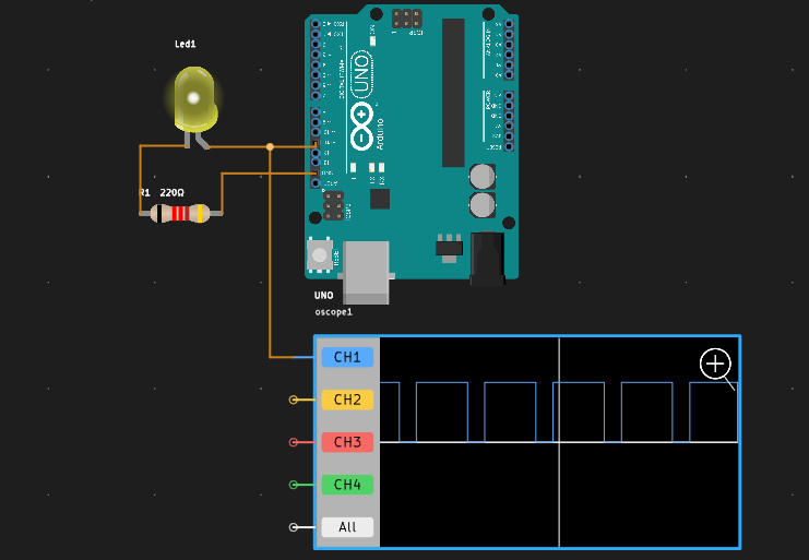
Pulse Width Modulation is a technique used to encode the width of pulses in a signal to represent an average value of a variable. In our case, we will vary the PWM signal's duty cycle to control an LED's brightness. The duty cycle is the percentage of time that the signal is high (on) compared to the total period of the signal.
2. Components RequiredFor this simulation, you will need the following components:
- An LED (Light Emitting Diode)
- A resistor (typically 220Ω to limit current to the LED)
- A PWM-capable microcontroller (like an Arduino UNO)
- PCBX online simulator
Access PCBX:Open PCBX in your web browser. You may need to create an account if you don’t have one.
Create a New Project:Join the EDA&Simulation Community, click on "Create New Project" and give your project a descriptive name, such as “PWM LED Brightness Control.”
Or just use the example project to recreate a new one.
The PWM Signal project code and details are here.
While running your simulation, observe the intensity of the LED. Note how it smoothly transitions from off to full brightness and back. If it doesn’t behave as expected, double-check your connections and the code for any errors.
5. ConclusionYou have successfully simulated a PWM LED brightness control project using the PCBX online simulator. This project demonstrates how PWM can be used to control the brightness of an LED effectively. You can experiment further by modifying the delays in the code or changing the resistance to see how it affects the brightness level.
Feel free to explore other PCBX simulations and enhance your electronics understanding! If you have any questions or need help, don’t hesitate to ask.


Comments
Please log in or sign up to comment.