Almost all the faucets around the world are still analog, mechanical valves, operated by hand to get water from the water supply networks. But an emerging market for a new type of touch-less smart faucet is growing now.
Kemet proximity sensors can be easily integrated in such solutions to detect the presence of human hand under the faucet and let water flow. That's the basic idea, which is fine for homes. But for public places like offices, restaurants, schools and hospitals, it will be useful to know how much water is consumed everyday, when is the peak demand or at which outlets more water is consumed/wasted.
The most important benefit of this solution is the elimination of bio-contamination from dirty hands in public restrooms/toilets.
This project demonstrates a solution of proximity sensor controlled smart water faucet with water usage sensing and monitoring both locally and remotely. The solution can also be converted into a water rationing station or paid water dispenser with few changes in hardware and firmware.
Kemet proximity sensor allows the entire system to stay in low power mode when no one is using water. Most of the power is only required when an user approaches to use the faucet and that activity is sensed by this sensor.
When all the electronics (except solenoid valve) powered from a 4.2 V LiPo battery, typical power consumption is as follows :
Standby sessioncurrent requirements
- Only proximity sensor consumes 680 uA
Active session current requirements
- Laser Module consumes 15 mA
- Tiva tm4c123 controller board consumes 45 mA
- Particle Argon for WiFi (IoT) connection consumes 190 mA
- Solenoid valve consumes 350 mA ( @ 12 volts)
Other units like latch relay, e paper display, sensors and ICs consume few mA of current for few seconds.
These numbers clearly show that, the standby mode has more than 2 orders of magnitude of lower power consumption than the active mode. (more on this is explained below on the device operation section)
The proximity sensor is small and it can sense through semi-transparent plastic materials, so the faucet manufacturers can easily integrate it inside for new faucet designs without making it obvious to the end users.
The combination of power saving, stealth installation and present sensing based action of this proximity sensor can be utilized for many other applications.
Video DemonstrationHardwareThe proximity sensor board KEMET SS-430L-N, NL has a JST SH 1.0 mm pitch 5 pin connector. But, I couldn't fine this cable where I live. So, I had to do this little hack and bring out the Vcc, Gnd and Signal lines.
Another problem was the extreme sensitivity and range of the sensor. I added some hot glue and an extra dome lens to reduce it down to around 20 cm. This also helped with splash proofing the unit.
The overall structural build of this project is fairly challenging for someone who has no 3D printer or access to makers workshop. Please keep in mind that, this is not a product, just a homemade prototype. So, I improvised to build this project on a Power Supply Unit casing of a desktop PC !!!
Hardware Build
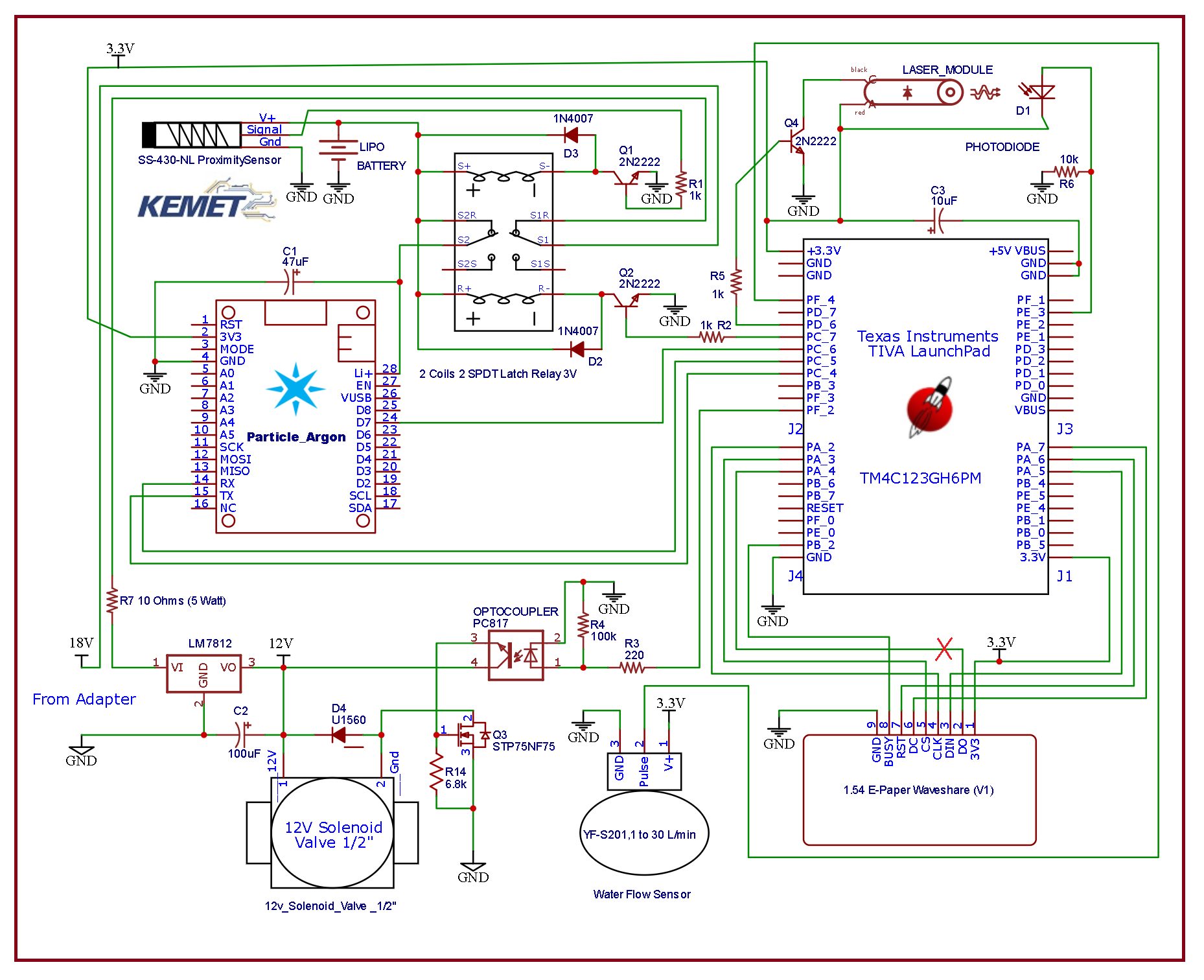
Hardware is built according to the schematic attached below :-
The device stays in standby power mode, while everything is powered down but the proximity sensor is waiting for the presence of human hand. Proximity sensor is powered directly from the LiPo battery. E-paper display will show visual instruction to the user about what to do !
When user puts his/her hand under the smart faucet, motion is detected and proximity sensor will generate a 200 ms high pulse. This pulse feeds into the base of a npn transistor and energizes the first coil (1-16) of a latch relay.
Latch relay is a special kind of relay, which does not require continuous supply to hold its contacts. This latch relay has 2 excitation coils and to separate SPDT contacts. Proximity sensor activates the latch relay to "set" position
This relay latches and connects the positive side of the LiPo battery to the Li input of Particle Argon board through one of its SPDT contact (4-6). Particle Argon board has an on board buck regulator which generates the the 3.3 volts for the rest of the electronics. The second SPDT contact powers up the solenoid valve driver circuit.
Next, few things will happen at once, Particle Argon will try to connect to Particle Cloud and Blynk Server through WiFi. These takes about 5-20 seconds, so the main loop of Particle Argon will not execute yet. But the user can not wait for the water ! So the second microcontroller Tiva tm4c123 starts to take care of everything while Particle Argon is connecting.
This flowchart explains the entire operation:-
- Water solenoid valve is energized through solenoid drive. This drive is driven with one GPIO of tm4c123, it takes 12-18 volts DC input from an external adapter.
- Frequency of the pulses from flow sensor is measured with one interrupt enabled input of tm4c123 mcu.
- E-paper display is updated with instruction, the display is driven with SPI 0 interface of tm4c123 mcu.
- Water quantity is calculated with timer and measured frequency.
This curve shown above is from the flow sensor datasheet, which shows the relation between pulse frequency generated by the sensor and corresponding hourly water flow amount. The curve is almost linear, so I derived this WATER_FLOW_CONSTANT of 2.06. It means, every second 2.06 ml of water flow is measured per Hz.
For example: if the frequency is sensed 35 Hz, about 70 ml of water has flown over last 1 second !
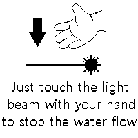
- User's command to stop water is sensed with interrupted laser beam, this is sensed by one of the ADC input of tm4c123.
- Next Solenoid valve is closed to stop water and interrupt is disabled
- Then water usage data is saved on EEPROM of tm4c123 with Tiva API
- Display is updated with latest water metering/usage data
- After that, tm4c123 will wait until D7 pin of Argon is high. When Argon is connected, data is send over Serial Bridge ( tm4c123 hardware serial 4 to Argon hardware serial 1 )
- Particle Argon pushes the water consumption data to Blynk Cloud over the internet. When user opens Blynk App, these information are pushed to the app from the cloud.
- Display is updated again with instruction image
- Finally, the entire system is turned off by energizing the second coil (2-15) of the latch relay to 'reset' the SPDT contacts, which disconnects the LiPo battery.
Step 1:Setting up Particle Argon
Before flashing firmware on Particle Argon, setting it up with WiFi and registering to Particle Cloud is necessary. This process involves following steps :-
- Download Particle IoT App on Smartphone
- Power up Particle Argon from a LiPo/USB port
- Open the app and signup/login to Particle Account
- Turn on Bluetooth and Scan the QR code on Particle Argon
- Provide WiFi credentials and save settings on Particle Argon
- Give newly assigned Argon any name
Official tutorial about this process can be found in the following link :-
https://docs.particle.io/quickstart/argon/
Step 2: Setting up Blynk
Once the Particle Argon is connected to Particle Cloud, new firmware can be flashed over the air (OTA) from the Particle Web IDE. But to connect this device to Blynk App follow these steps :
- Download Blynk IoT App on Smartphone
- Open Blynk App and choose new New Project with (+) icon
- Choose your device to "Particle Photon" and tap 'create'. Particle Photon setting works for Particle Argon too.
- An authentication token will be sent to your email
Authentication token is an unique large string, something like this :
s8dfsd7HHGHJBJHNJKlioi8yu8u87yUY8U (just an example)
It is used to identify and authenticate a device to Blynk cloud. See the firmware and programming section below about how to put auth token on code !
Check the following link for more details on Blynk Setup :-
https://blynk.io/en/getting-started
Firmware & ProgrammingThere are two separate codes for this project. One is for Tiva tm4c123 which is written on Energia IDE, another is for the Particle Argon which is written on Particle Web IDE.
To use Blynk app with Particle Argon, you must include Blynk Library to your project and paste the Authentication Token send to your email from the previous step (Blynk Setup)
- Get the code for Particle Argon here.
Energial IDE is an Arduino like IDE for some Texas Instrument microcontrollers with easy to program support with Arduino APIs and functions. It also supports TIVA APIs for other peripheral configurations
- Get code for Tiva tm4c123 here
Water usage information for last session, net water consumption of all sessions and historical water usage info can be checked from the mobile app. These data comes from Blynk Cloud and data is sent there with Particle Argon.
Get this app configuration by following these steps :
- Download Blynk from Google Play or App Store
- Create Account/Log in to the app
- Click on the "QR" button and allow camera access to Blynk
- Scan the following QR code to get this app setting on your Blynk
Note 1 : This app will not allow you access to my hardware, you have to make your own hardware and get Authentication Token from Blynk and use that to program your Particle device to access your hareware
Note 2 : To avoid confusion between ml and Liter, all consumption information shown on app is in Liter. For example 1430 ml will show 1 Liter. That does not mean that 430 ml is not accounted for. That amount is still accumulated to net water consumption. For example, if the next session's consumption is 2734 ml, you will see the net meter will increase by 3 Liters.
Note 3: Originally, water metering is done in ml on tm4c123 and the maximum value can be 4,294,967,295 ml (maximum 32 bit unsigned integer) or 4.2 million Liters. Milliliters is converted to Liters by dividing with 1000, so the fraction of liter is not shown. But that amount is still added and saved in EEPROM and send to app
Note 4: The water flow sensor datasheet says the reading may have an error within +/- 10%
There is much more to do but it's time to end this project. I tried my best to meet all the criteria for this contest.
Lets end this project with talking about some of the challenges I faced while building this. First, the proximity sensor was very sensitive and I somehow tamed it !
Then, I had some issues with the plumbing works and two major water spillage during shooting, as I couldn't secure the hose strong enough with the solenoid value. The flow sensor leaked near its seal during water flow. I also blew one 12 volts power supply from the water splash ! Luckily, all the electronics were saved.
As for future works, I would like to eliminate the need of using 12 V supply by using low voltage solenoid valve. Also, find a way to use one microcontroller solution instead of two, cut down BOM cost for a practical design.
My ideal design will be a self-powered solution with one of these Hydro Generators and super capacitor that will require no power supply !


_zhWsCcSEcl.jpg?auto=compress%2Cformat&w=48&h=48&fit=fill&bg=ffffff)


Comments
Please log in or sign up to comment.