Almost every modern microcontroller comes with power saving / sleep functions to reduce the power consumption of the system.
Benefits of Low Power/Sleep in projects/products
- Longer battery life from months up to years
- Less maintenance
- Environment friendly, reduces carbon emission (think about billions of microcontrollers products)
- Reduces operation cost
- Enables remote operation
But there is a problem, when you build a project using a development board rather than just using the bare microcontroller, sleep is not going to save power.
Most development boards have a power LED which is always on. There are debugging circuits and sensors on board which consume power even though the primary MCU is sleeping. Another culprit is on board voltage regulator which draws quiescent current all the time. Development boards are USB powered and run on 5 volts but the MCU on the board usually runs on 1.8 Volts to 3.6 Volts. Lots of power is wasted even when the main MCU is sleeping.
Here is a nice article on this matter from Sparkfun.
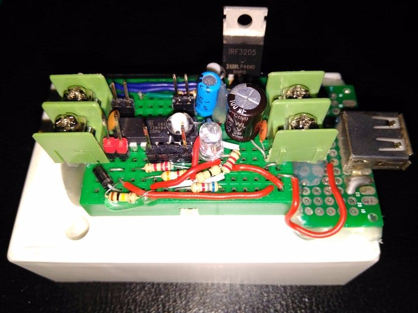
The solution is simple: use another bare bone low power microcontroller to control the power for the entire development board. Here, my solution is to use a Attiny 84 to periodically on and off the development board as required. The timing can be user programmed. The system will power down both itself and the development board which is powered through it.
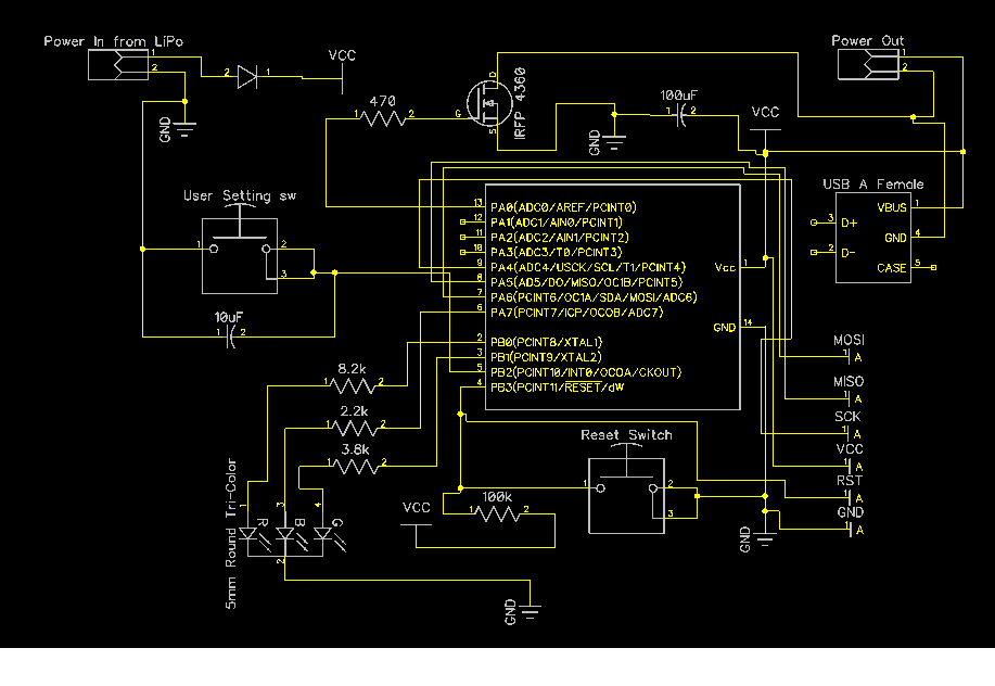
The system is built using an Attiny84 microcontroller, an RGB LED for status, 2 push switches for user setting and reset, one n-MOSFET for power control, a few bypass capacitors, resistors and a reverse polarity protection diode.
Operating voltage range is 3 volts to 6 volts, making it ideal for 2/3/4 AA or AAA battery-powered / USB-powered / Single cell LiPo-powered (with/without Solar) solutions possible.
Power can be input through Screw Terminal Blocks and power can be fed to external circuits through Screw Terminal Blocks/USB Female port making it a plug-n-play solution for any Development Board.
Before using the Attiny84 with Arduino, it needs to be prepared. First, download the Attiny Arduino Core. Next, follow the instruction from this tutorial.
You will need another Arduino as ISP programmer to do this, any AVR ISP programmer should work!
In case an Uno is used as ISP programmer, connection should be as follows:
For any other ISP programming connection should be as follows:
- Prog MOSI >> Attiny84 MISO
- Prog MISO >> Attiny84 MOSI
- Prog SCK >> Attiny84 SCK
- Prog SS >> Attiny Reset
The code is written in Arduino IDE with some AVR Register Configurations. Here is a flowchart of what basically happens in the program:
I have functionized groups of tasks for ease of understanding. In the setup function, I/O initialization is done first. Next, user input is taken for programming a custom timing of off and on times. The user switch is connected to the INT0 which activates on the falling edge and increases a volatile variable for performing input accepting task and showing that output with LEDs.
The user switch works on both the press and press & hold basis to take seconds/minutes/hours of off time and on time. Next the LED blinks to verify the user that the input is OK.
Then the ADC is disabled, since there is no use for ADC here.
Finally the watchdog is configured to bark!
In the void loop, the CPU goes to sleep. When the watchdog timer expires, the CPU wakes up, disables sleep, updates time and checks if the off time has expired or not. If the off time is over, then the MOSFET is turned on for the whole on time.
Next the CPU goes to sleep until the next watchdog timeout. Here, I have configured the timeout approx 1 second. The LED blinks briefly every second with RED, blinks GREEN every minute and BLUE every hour. This ensures the system is up and running.
Configuring the SystemThe On/Off Timing for the external load is configured according to user's wish during power up.
There is only ONE INPUT USER SWITCH (except RESET) and ONE OUTPUT RGB LED.
The trick is to use the same switch as:
- PRESS & RELEASE IMMEDIATELY Mode
- PRESS & HOLD DOWN Mode
Off Time represents the duration while the external load will stay powered off, which can be a combination of seconds, minutes & hours.
On Time represents the duration while the external load will stay powered up, which can be a combination of seconds, minutes & hours, too.
Here is the start up sequence to configure the system:
After the Off-Time is set, a similar procedure is required to follow to set On-Time.
When setting is complete, the LED will blink in colors to represent total off and on time so the user can verify.
Here are the rules for the RGB LED glow/blink:
The first blink is always ignored. After first blink in each color:
- consecutive RED blinks count as Seconds
- consecutive GREEN blinks count as Minutes
- consecutive Hours blinks count as Hours
Off-time is set first, then press and release to enter on-time (RGB all blinks). On-time is set next (similar to off-time setting method). When setting is done, the LED blinks to verify off-time and on-time in the respective colors. Both off and on time setting are shown separated by RGB blinks in between them.
E.g. Suppose I want to set Off time of 5 Sec, 4 Min, 0 Hrs: I will do 6 red blinks, 5 green blinks and 1 blue blink. See the action video for better understanding.
Action VideoTiming Setting: few seconds on-off cycle
Timing Setting: One Minute on-off cycle
Power Saving VerificationAn Arduino Uno is powered through the sleep controller and here are the results:
26.6 mA or 26600 uA when active and when off only 8.6 uA. Ratio is about 3100!!
Scope of ImprovementsThere are other variants of interesting solutions possible to make.
- One method could be where the development board's MCU will communicate with the sleep controller's MCU asking to initiate a sleep for a given duration like this:
- Watchdogs are not very accurate for timing. In my case, my minutes were off by 9 seconds due to the inaccuracy of WDT, delay calls, execution time for the code. A solution to this problem is to use a software time correction/compensation or use an external RTC for calculating elapsed time.
- Using Battery Packs start with a slightly higher rated voltage will provide longer battery life. For example, a 5 volts USB powered/programmed development board will run fine within 4-6 volts range. 4AA Battery packs are best choice for extracting maximum juice from battery.
- There is a RC (2.2k + 10 uF) network parallel to User Input Switch on INT0/Arduino Pin 8/Attiny84 pin 5 for Hardware Debouncing. This ensured the press switch does not flicker during HIGH to LOW transition.
- Bypass Capacitor is a must on Vcc and Gnd pin of Attiny84, otherwise the MCU might restart when external load sucks too much spike juice.
- Since, the n-MOSFET used here is not a logic-level MOSFET, voltage drop becomes significant for current greater than 100 mA. With appropriate MOSFET and powerful Battery packs, several Amps can be transferred.
- 4AA battery pack gives slightly higher than 6 volt during fresh start, which is higher than the Absolute Maximum of Attiny84. A diode in series may help to safe limit the supply voltage.
- There is contact resistant loss associated with breadboard design and power terminals, a soldered design on protoboard/pcb will be more efficient.
- Sometimes the user switch, LED blink might get messed up, resetting the MCU for restart will help then.
- Watch dog timer can be off by up to +/- 20 % and temperature dependent, so timing is not perfect.
- Brown out detection is disabled, on rare cases flash program might get corrupted
- Reliability tested for 8 hrs with around 1 hrs, 1 min, 3 sec off-time and 12 seconds on-time and system was found operational without issues. If there is a possible bug in the code, timing might mess up for other combinations.
There you have it, one solution to all power saving problems with prototyping. Save battery, save on costs and save the environment!
ReferencesSome codes are used from AVR Library Dev page and Marcelpost Wiki


_baVEVgguW1.jpg?auto=compress%2Cformat&w=48&h=48&fit=fill&bg=ffffff)


_3u05Tpwasz.png?auto=compress%2Cformat&w=40&h=40&fit=fillmax&bg=fff&dpr=2)


Comments
Please log in or sign up to comment.